Ever wondered if you could tweak the shape of the component using suggestions? In the previous post, we discussed Topology optimization. if you haven’t read about Topology Optimization you can read it here. In this post, we are going to discuss topography optimization.
What is Topography Optimization?
Topography optimization is the modification of the shape of a component to meet the design requirement.
Performing Topography optimization
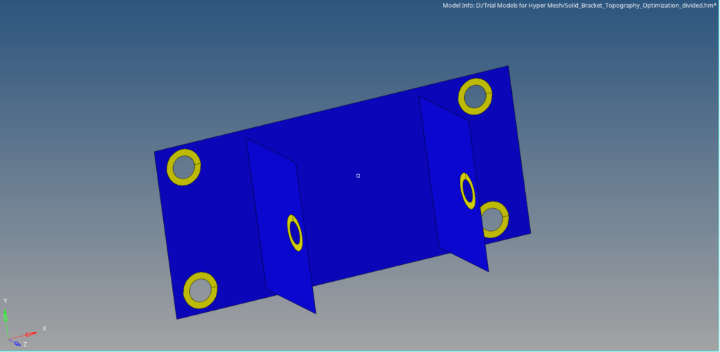
For this tutorial, we will be using the 2D meshed model of the same bracket used in topology optimization. We will segregate the component into two regions design and non-design region. Design region is the region where shape modification is allowed whereas a non-design region is the region where shape modification is not allowed. The yellow area in the bracket is the Non-Design area and the blue area is the Design area.
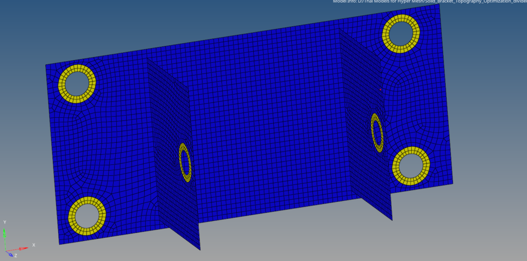
Meshed Model
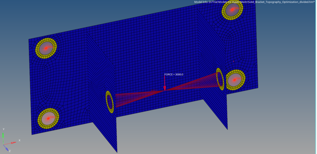
For this tutorial, we will use a bracket with dimensions 164 x 74 mm. The model is meshed using Quad elements of size 2. Only shell mesh is used. The geometry will be divided into two regions Design and Non-Design regions as shown in the image below. The holes on which load and constraints will be applied will be kept under the non-design region, and the rest of the body will be kept under the design region.
Boundary Condition
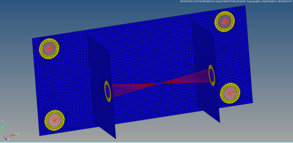
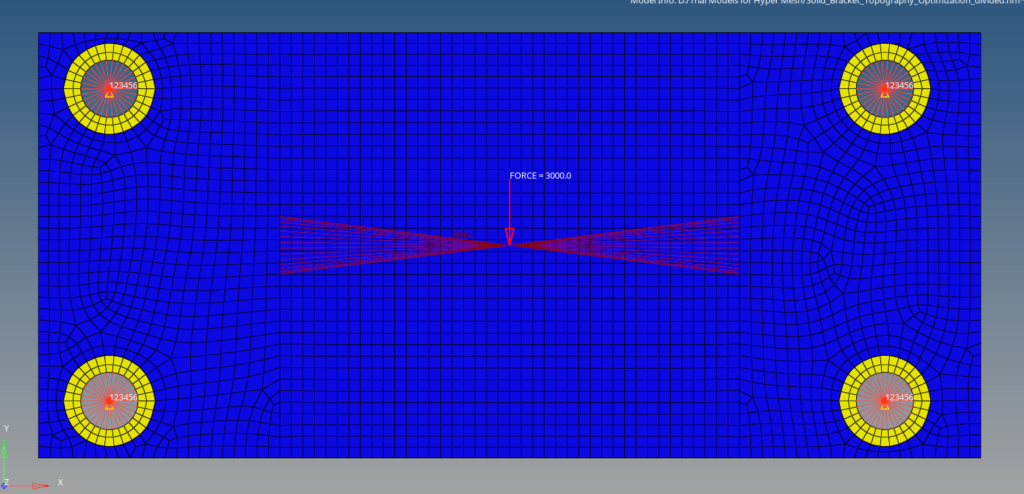
We will create two load collectors one for applying load and the other for applying the constraints. Create a load collector by right-clicking on the white browser area and then going to create -> Load collector. Next, create a load collector named Load. Now apply a force load of 3000 N in the negative y direction on the RBE2 element created on the two holes as shown in the image below. We can create force load by going to Analysis -> force.
Next, we will create a new load collector by right-clicking on the white browser area and then again going to Create -> load collector. We will name this load collector constraint. We can create constraints by going to Analysis -> constraints. We will apply these constraints to the four holes on the flat face as shown in the image below.
Analysis Setup
Now we have to create materials, properties, design variables, responses, constraints, and objectives for the optimization. First, we will create material and property by right-clicking on the white browser area and then going to Create -> Material. We will use steel as our default material.
For creating property we can again right-click on the white browser area and then go to Create -> Property. We will create two properties Design and Non-Design, both with card images as PSHELL.
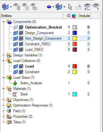
We will create a load step by right-clicking on the white browser area and then going to Create -> Load Step. We will name this load step as Static analysis and select the analysis type as Linear Static and reference the constraint under the SPC and the Load under the load field. If you want to learn about Linear Static Analysis you can check out this post here.
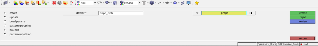
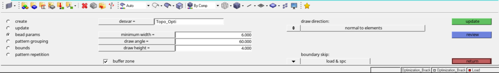
We will then create a topography design variable by going to Analysis -> Optimization -> Topography. We will name this variable Topo_Opti. We have to select the property of the Design part while creating this variable. I have used minimum width as 6 and draw height as 4 under parameters. Refer to the image below.
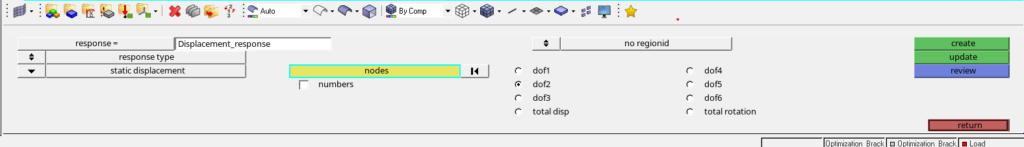
After this, we will create responses for this optimization. For creating responses we can go to Analysis -> Optimization -> Responses. We will create a response named Displacement_response as shown in the image below.
Next, we can create constraints for the responses, but for this tutorial I am not using any constraints.
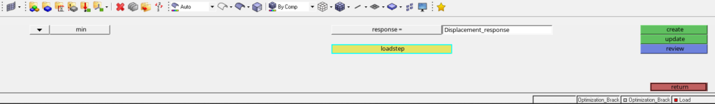
Next, we will create the objective for optimization. We can do this by going to Analysis -> Optimization -> Objective. We will name this objective as objective. Refer to the image below.
Performing optimization
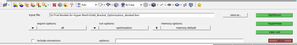
Now we have applied the boundary conditions and created the variables necessary for optimization. We can now proceed to run the Optimization. For this, we have to go to Analysis -> Optistruct. Then select export options as all and the run options as optimization and click on Optistruct to run the optimization as shown in the image below.
If you can’t see the Optistruct option go to Preferences -> User profile and select Optistruct.
Output
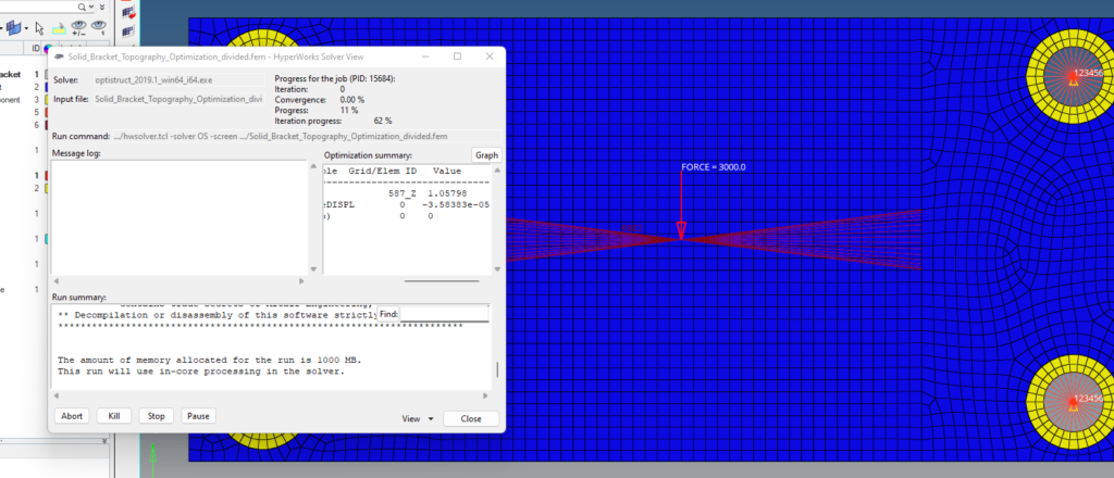
After you click on Optistruct a pop-up window as shown in the image below will appear.
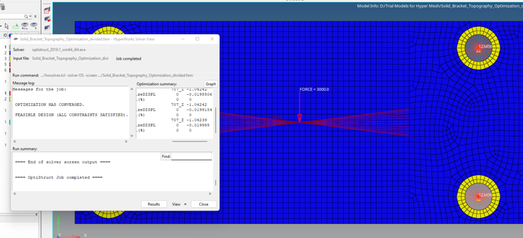
After the run is complete we can view the results by clicking on results. A pop-up window of hyperview will open as shown in the image below.
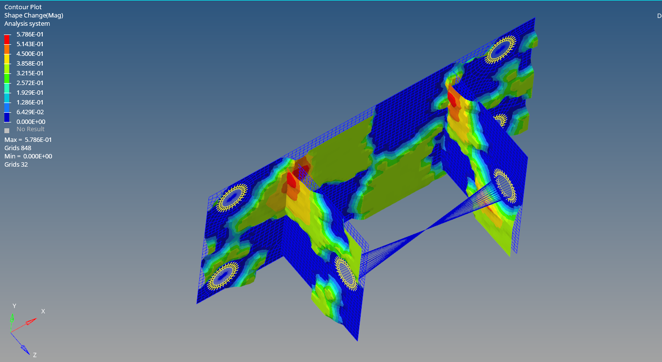
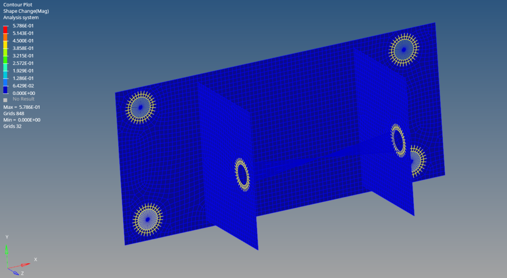
As you can see from the image below the shape of the bracket has been modified by the last iteration. We can take this shape into consideration and remodel the component.

Refer to the video for more clarity on the Topology optimization.
This is all for this post. Comment your thoughts below. Don’t forget to follow my Facebook and Instagram pages for regular updates. See you all in the next post. Till then keep learning.