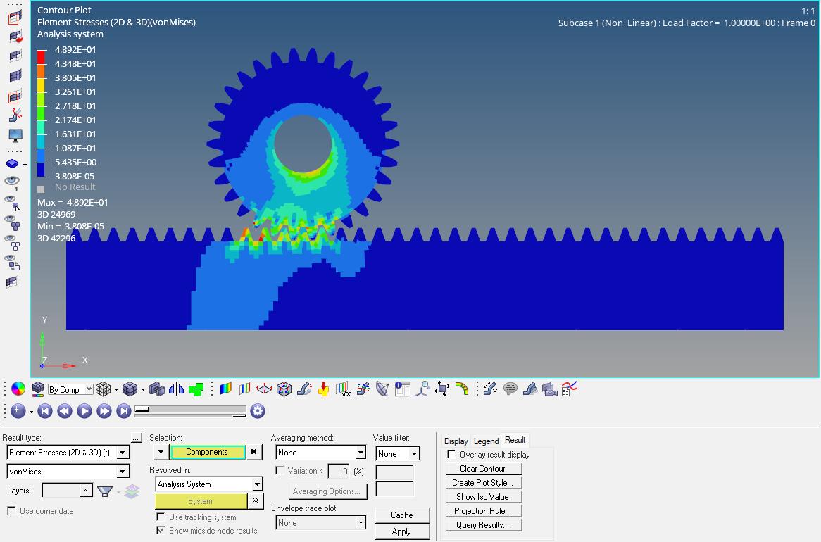
In the previous posts, we have seen majorly about Linear analyses. If you have not seen those posts you can check them out here. In this post, we will see something different from the usual analyses. In this post, we are going to perform a Non-Linear Contact Analysis.
So let’s start by understanding what Non-Linear Contact Analysis is and then we will proceed to perform the analysis.
What is Non-Linear Contact Analysis?
Nonlinear contact analysis is a crucial type of analysis, especially when dealing with complex component interactions. It considers the effects of geometric nonlinearity, material nonlinearity, and contact interactions.
To simplify, non-linear Contact Analysis describes cases where the input and output are not related linearly.
In simpler terms, it’s used when the load path between parts of an assembly changes due to the load direction. A common example is a bolted flange, where the contact between the bolt and the flange changes as the load is applied.
Performing Non-Linear Contact Analysis
In this tutorial, we will use a rack-and-pinion assembly to perform Non-Linear Contact Analysis, as shown in the image below.
Meshed Model
For this tutorial, I have meshed the Rack and Pinion using 3D Hex elements as shown in the image below.
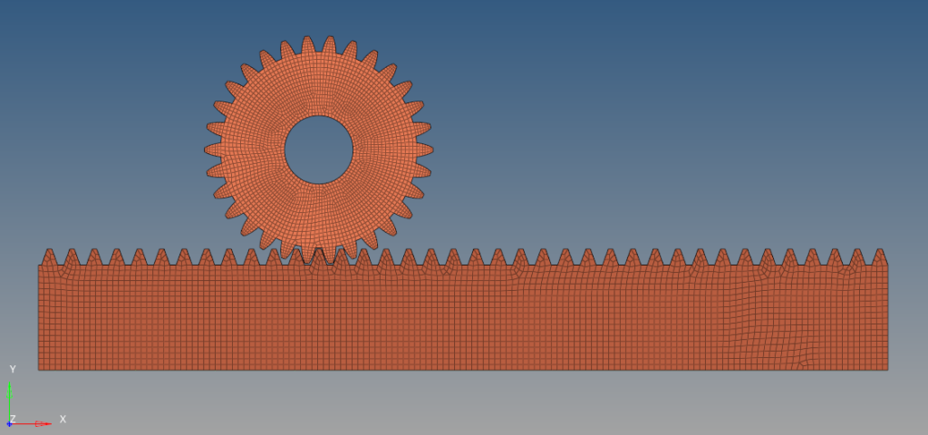
We will fix the pinion and a force will be applied to the rack.
Boundary Condition
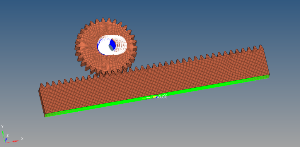
We will fix all the nodes on the inner face of the pinion. For this, we can right-click on the white browsing area and then go to Create -> Load Collectors. We will name this load collector Pinion_Constraint. To create this constraint, we can go to Analysis -> Constraints, select the inner face of the pinion and all the degrees of freedom, and then click Create.
Next, we need to create RBE2 elements to apply load on the bottom face of the rack. For this, we can again right-click on the white browsing area and then go to Create -> Component, we will name this component RBE2, and then we can go to 1D -> Rigids and select all the nodes on the face of the rack, select all the degrees of freedom except that along the X-axis and click create.
Post the above activities the Model should be like something shown in the image below.
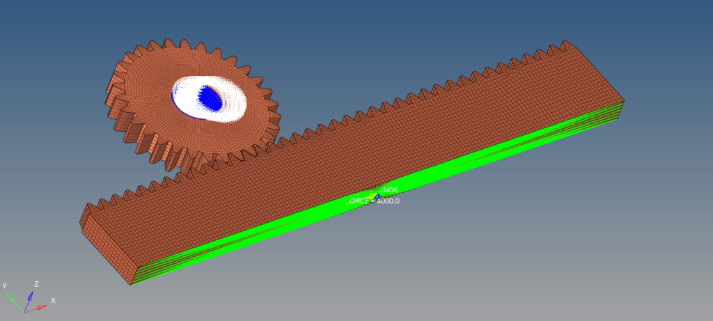
We will now create the load which will be applied on the bottom face of the pinion. For this, we can right-click on the white browser area and then go to Create -> Load Collector. We will apply a load of 4000 N on the master node of the RBE2 element as shown in the image below. We can do this by going to Analysis -> Forces, and then selecting the master node, and direction as X-axis and then putting the magnitude as 4000N, and then clicking on Create. Refer to the image below for more clarity.
Analysis Setup
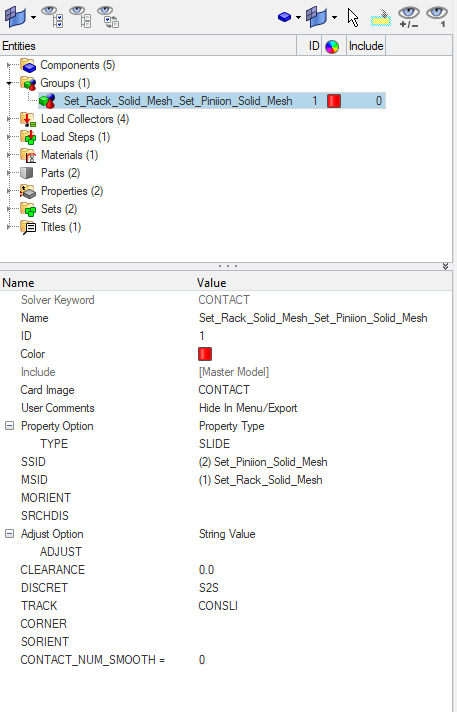
Next, we need to create a contact between the Rack and Pinion. If the contact browser is not visible, we can go to View -> Browsers -> Hypermesh -> Contact. Now we will define auto contact for the rack and pinion. We can do this by selecting the two components from under the components and then right-clicking and selecting Auto contact. We will select the contact type as SLIDE. The pinion elements should be the slave elements and the rack elements should be the master elements. Set the DISCRET field to S2S and the TRACK field to CONSLI.
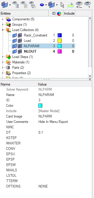
Next, we need to create an NLPARAM Load collector. We can do this by right-clicking on the white browser area and then going to Create -> Load Collectors. We will name this load collector as NLPARAM select the card image as NLPARAM and set DT as 0.1.
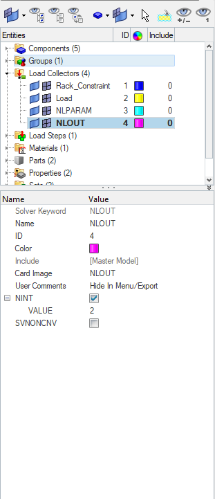
Next, we need to create an NLOUT load collector. We can do this by again right-clicking on the white browser area and then going to Create -> Load Collectors. We will name this load collector NLOUT select the NINT and put its value as 2.
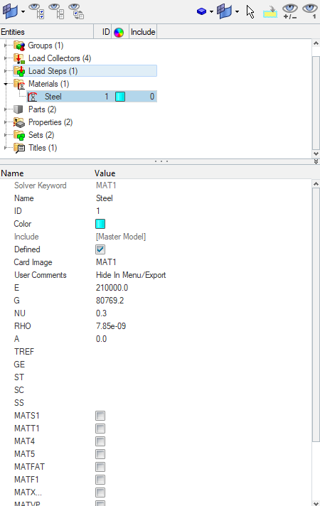
Next, we will create the Material and the properties for the rack and pinion. We will use Steel as the material here. We can again create material by right-clicking on the white browser area and then going to Create -> Materials. We will name this material as steel and use the default value of steel.
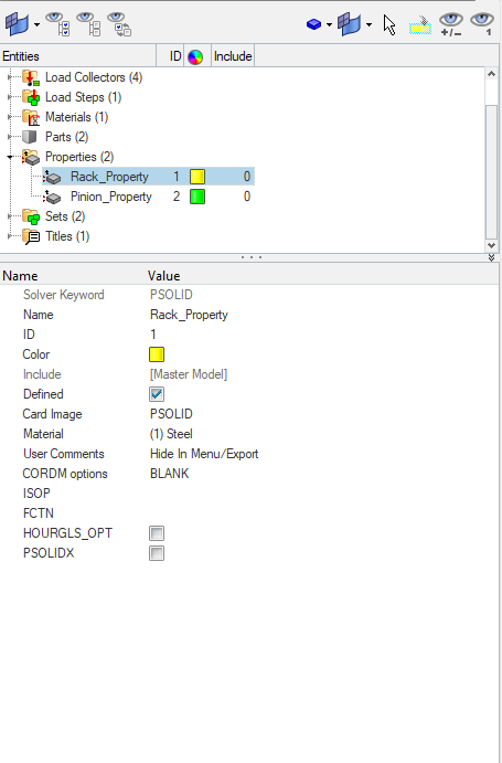
Next, we will create the properties for rack and pinion. We can again do this by right-clicking on the white browser area and then going to Create -> Load Collectors. We will name these properties Rack_Property and Pinion Property and select the card image as PSOLID.
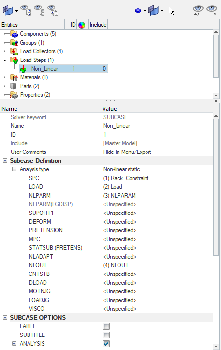
Next, we will create a Load Step for Non-Linear Analysis. We can create this load step by right-clicking on the white browser area and then going to Create -> Load Step. We will name this load step as Non_Linear and select the Analysis type as Non-linear static. We will reference the Pinion constraint under the SPC field and the Load under the Load field, we also need to reference the NLOUT and NLPARAM load collectors under their respective fields.
Performing Analysis
Now we will perform the analysis. For this, we can go to Analysis -> Optistruct and then select the run option as analysis, and then click on Optistruct.
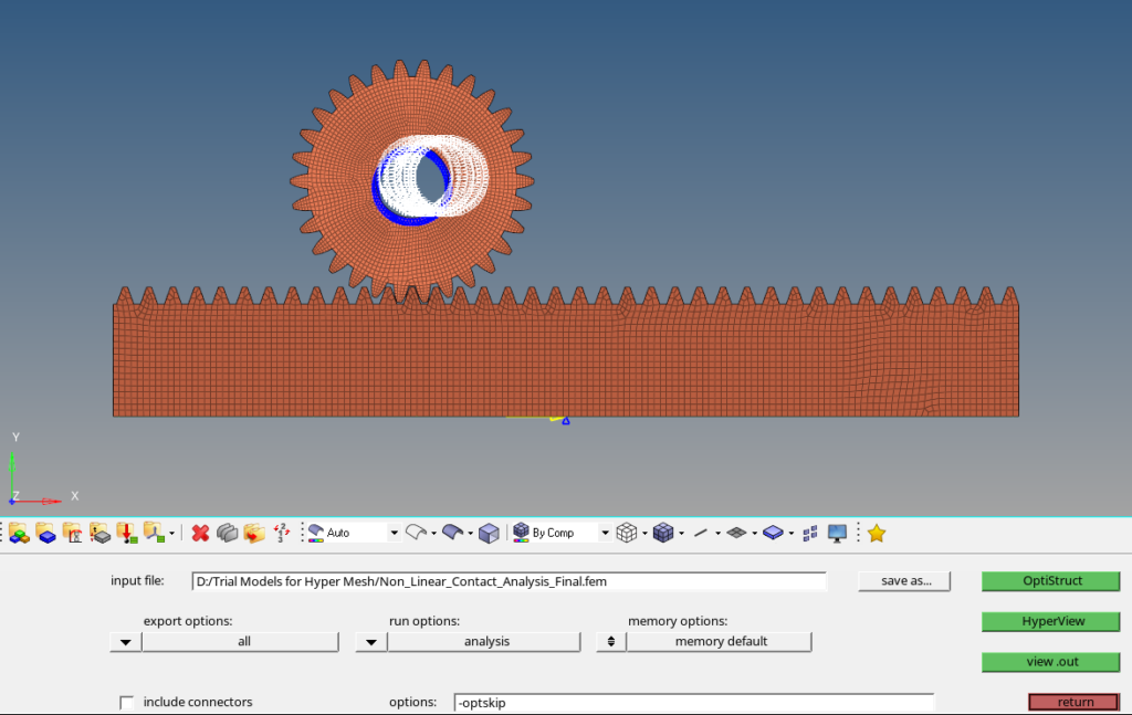
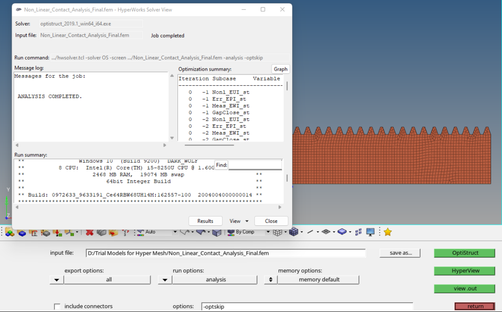
Once we click the Optistruct button a pop window like the one shown in the image below will appear.
Output
Once the solver run is completed we can view the output values we can also go to View -> Output file as shown in the image below.
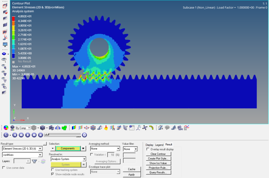
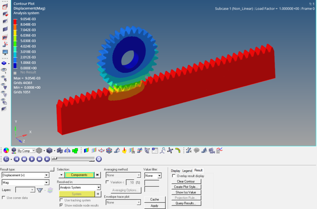
We can now view the results by clicking on Results. This opens a Hyperview window which is used to view the results of analysis.
You can also refer to the video below for more clarity.
This is all for this post. I’ll see you all in the next post. Don’t forget to follow my Facebook and Instagram Pages for regular updates. Until then, keep learning.
