
Being familiar with the toolbar in Hypermesh helps in evaluating the available options for improving your mesh, and connections, or using different settings for analysis.
In this post, we are going to explore some of the most used options while meshing from the area highlighted in orange in the below image.
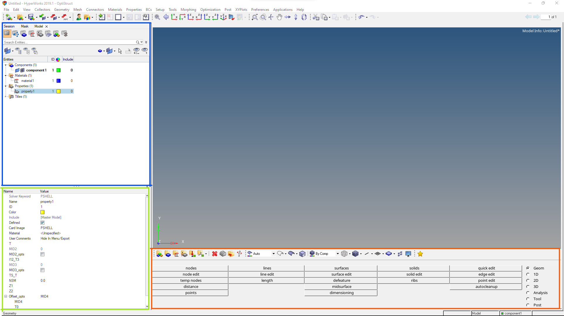
Geometry:
We will start with the geometry editing options. Under geometry editing options you have node, line, surface, solid, edge, and edit options for all of them.
Under nodes, we can create nodes using lines, circles, or coordinates. In node edit, we can associate, align or move the nodes.
Under the lines option, we can create a line using coordinates, nodes, vectors or other lines. In line edit, we can merge, split or extend lines.
The surfaces option is used to create different types of surfaces. In surface edit, we can trim, untrim, and extend surface, while in edge edit we can toggle, replace, and unsplit edges. The same goes for Solid and solid edit options. In addition to these, there is a quick edit option which contains a whole lot of options most notable among them is the washer split which is frequently used to encompass critical areas around holes.
1D:
Under 1D we have rigids, connectors, edit element. These options are used to connect different types of elements and create elements.
2D:
Under 2D we have Automesh, ruled, spline, edit element. Automesh is the most used option here, you can either select elements or surfaces to mesh under this option. Ruled mesh is used when we have lines, node list, or a node list and a line. The spline can be used when we have a group of nodes or lines in any orientation. Spin is used to spin the elements about an axis. The edit element option helps in editing elements with the following options: create, combine, and split elements.
One question that might arise in your mind is why do we need other meshing options when have automesh in 2D? It is because we can use them to mesh areas without surface and it comes in handy sometimes.
3D:
Under 3D we have tetra mesh, connectors, solid map, linear solid, solid mesh, edit element. Tetramesh contains the options to produce tetramesh directly by solid volume or by enclosing the surface with 2D elements. The solid map and solid mesh option is used to create 3D elements by dragging 2D elements along a path. the connector option is to make connector elements like bolts, welds, etc. The edit element option helps in editing elements with the same options as in 2D.
Read more about 1D, 2D & 3D elements here.
Analysis:
Under Analysis, we have constraints, forces, moments, and control cards. constraints, forces, and moments are self-explanatory. Control cards are used to input and output parameters.
Tools:
Under the Tools section, we have check elements, edges, mask, reflect, rotate, translate, numbers, faces. Check elements used for checking warpage, aspect ratio, skew, tetra collapse and Jacobian for 2D and 3D elements. Edges are used to find if there are any open edges or nodes which need to be equivalenced. Mask is used to hide the selected elements or nodes from the display area. Reflect, rotate and translate do exactly as the name says. Numbers is used to switch on/off the identification number of elements or nodes.
You can also refer to the below video for a better understanding of the topic.
This is all for this post, see you all in the next post. Don’t forget to follow my Facebook and Instagram pages for regular updates.