In all our previous posts, we have used Optistruct as a solver for our FE model. In this post, we will solve our FE model using the Nastran solver. For this post, we will use the same beam model from the last applying moment tutorial. If you have not seen that post, you can check it out here.
The Preparation process will be the same as in the previous tutorial.
Applying a moment to a structure
In this tutorial, we will be applying the moment to a beam by fixing it at one end.
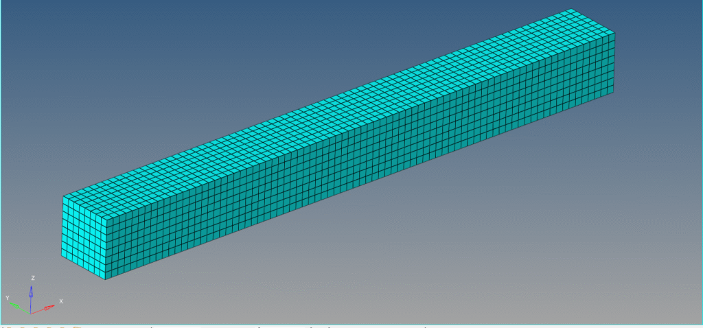
Meshed Model
In this tutorial, we will be using a beam of dimension 8 mm x 8 mm x 80 mm meshed using Quad elements of size 1 as shown in the image below.
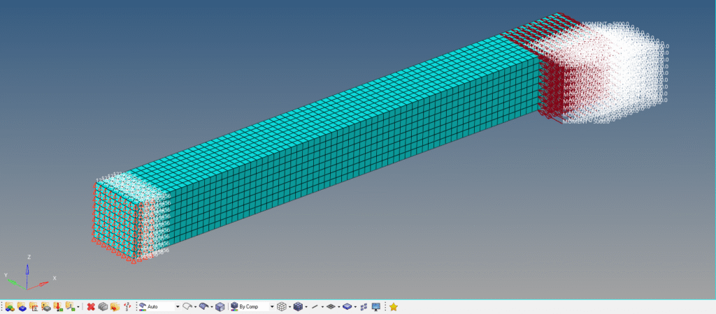
Boundary condition
We will constrain one face of the beam. For this, we can right-click on the white browser area and then go to Create -> Load Collector. We will name this load collector as Constraint. Next, we can go to Analysis -> constraints and select all the degrees of freedom to constrain, and then click create.
Next, we will apply the moment to the beam. For this, we can again right-click on the white browser area and then go to Create -> Load Collector. We will name this load collector Moment. We can now go to Analysis -> Moments and select the nodes on which we want to apply the moment, and then select the direction of the moment. Kindly note that the direction of the moment is the
Analysis Setup
We need to define Property and material for the model. For this, we can right-click on the browser area and then go to Create -> Material and name this material as Steel. We will use the default material steel here as shown in the image below.
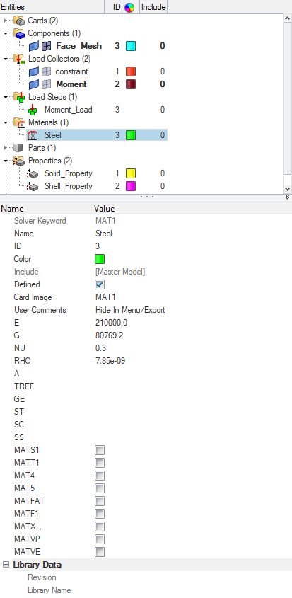
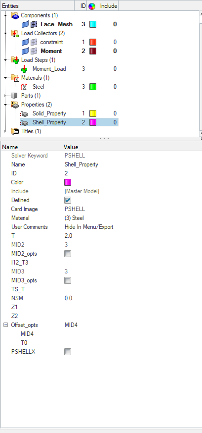
Next, we will create the property for the model. Again, we can right-click on the white browser area and then go to Create -> Property and name this property as Shell property. We will use the shell element thickness of 2.
Selecting Control Cards
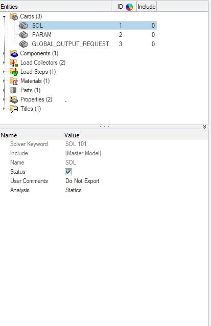
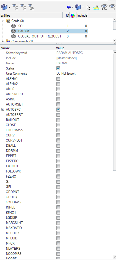
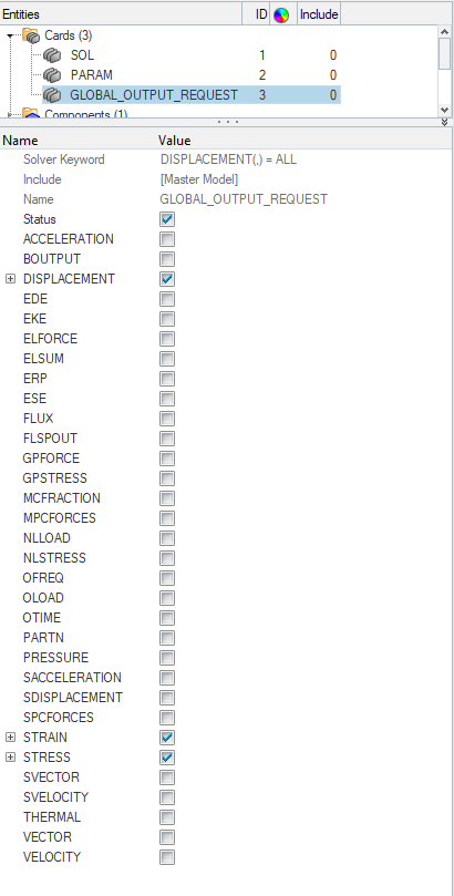
We need to select certain cards if we want to solve our model in Nastran. First, we need to select the Solution card. For this, we can go to Analysis -> Control Cards, and then select SOL 101 (Static). Next, we need to select the Output Requests card. For this, we can go to Analysis -> Control Cards -> Global_output_Request, and then select Displacement, Stress, and Strain. Refer to the images below for more clarity.
Performing Analysis
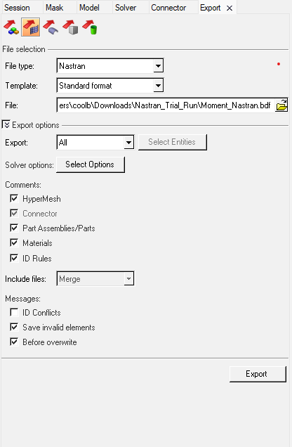
Now this is the place where we will have a difference, as we will be using Nastran as a solver for solving our FE model, we need to export our model in a format that Nastran can process. For this, we can go to the Export option and select the File type as Nastran and select a suitable location, and name for our Nastran file as shown in the image below.
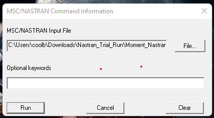
Next, we need to open Nastran and select the exported file, and click Run as shown in the image below.
Output
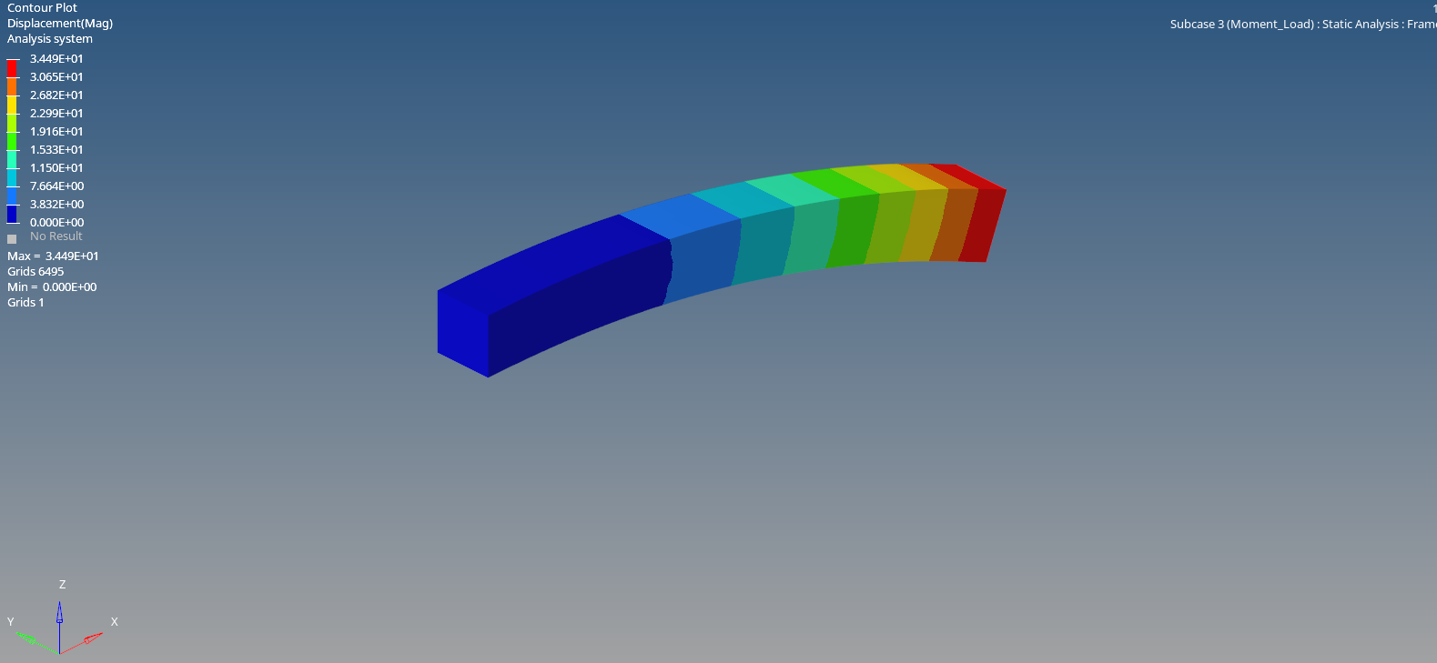
After the run is over, we can click on Results to view the results in Hyperview as shown in the image below.

So the process for solving the FE model remains the same except for the end part where we have to export the data of the model in a format which the solver can understand.
This is all for this post. I will see you in the next post. Don’t forget to follow my Facebook and Instagram pages for regular updates. Till then, keep learning.