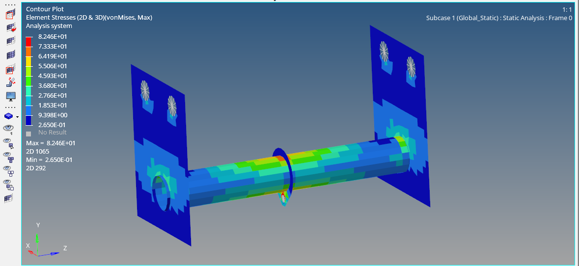
In the previous posts, we have seen about Inertia Relief Analysis. If you have not seen those posts you can check it out here. In this post, we will see something different from the usual analyses. In this post, we will perform a Global analysis of an assembly to derive the reaction forces on a component of the assembly.
So let’s start by understanding Global and Local Analysis.
What is Global and Local Analysis?
Global Analysis as the name suggests is an analysis at the global level. But what is this global level? The global level here means that the analysis is performed on the assembly whereas Local analysis means the analysis is performed on a specific component of the assembly.
So, how do we perform local analysis if only the boundary conditions are given for the global case? Follow this post to learn.
Performing Global Analysis
For this tutorial, we will be using a rod fixed between two brackets which are fixed and the load will be applied on the assembly through a hanger.
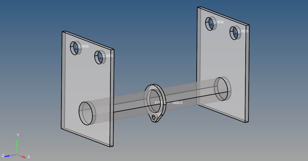
Meshed Model
For this tutorial, we will use two brackets, one rod, and a hanger meshed with 2D mixed elements as shown in the image below.
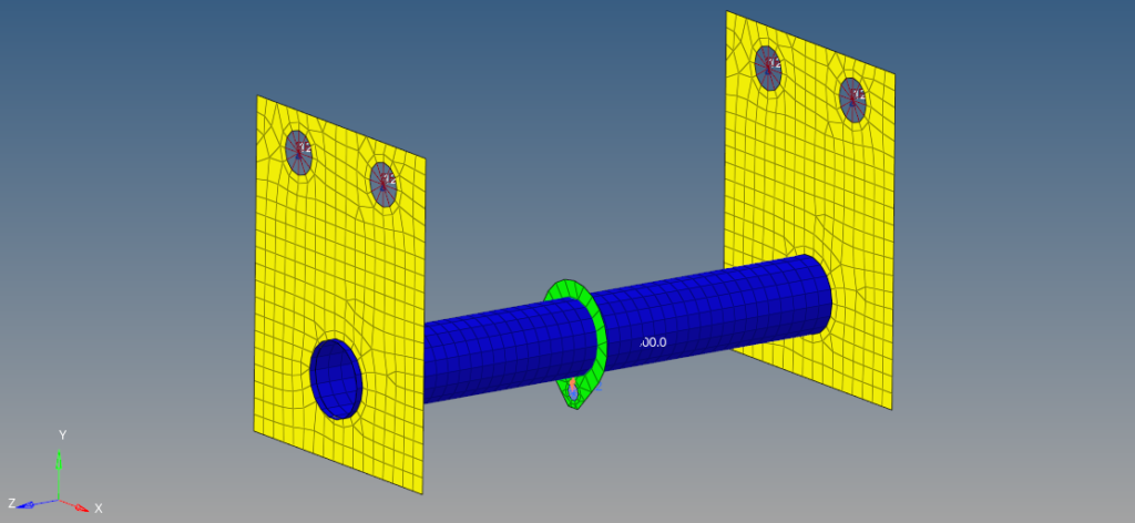
Boundary Condition
We first need to create RBE2 elements for applying the boundary conditions. We can do this by right-clicking on the white browser area and going to Create -> Component, we will create two RBE2, one for constraining the brackets and one for applying the load.
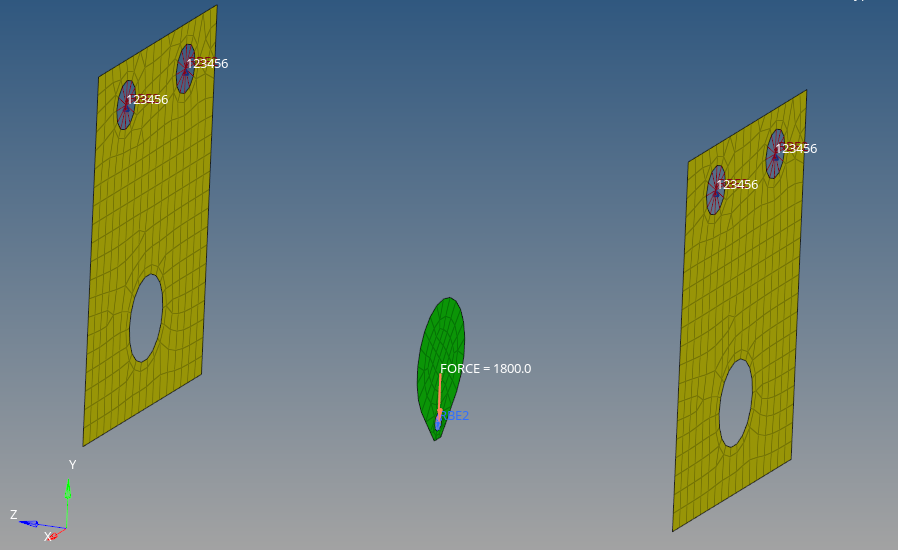
We will create a load collector named constraint to constrain the bracket. We can do this by right-clicking on the white-browser area and then going to Create -> Load Collectors. We will constrain all the degrees of freedom of the master nodes’ two holes on each of the brackets by going to Analysis -> Constraints as shown in the image below.
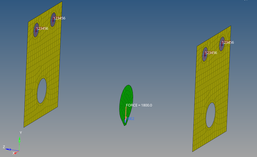
Next, we will create the load collector for applying load on the RBE2_Load. For this, we can go to Analysis -> Forces. After this, we can select the master node of the hole in the middle hanger and apply a load of 1800 N on it in the negative Y-direction.
Analysis Setup
Now we will create material and properties for the bracket and bolt. We will use Steel material for all the components.
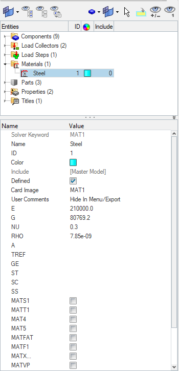
We can create material by right-clicking on the white browser area and then going to Create -> Materials. We will name one material as Steel as shown in the images below.
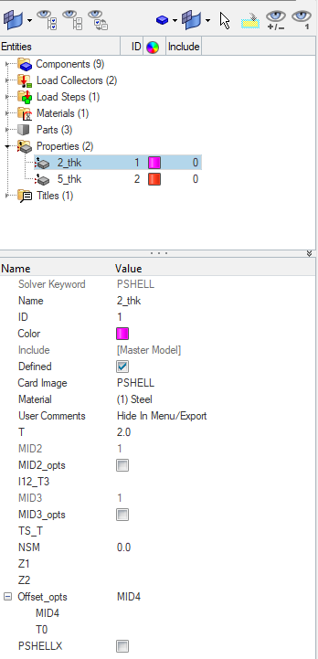
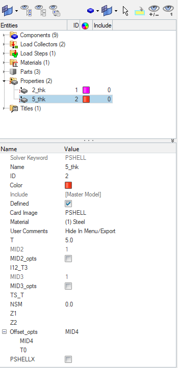
Next, we need to create properties for the rod, middle hanger, and bracket. For this, we can again go to the white browser area and then right-click on the white browser area and then go to Create -> Properties. We will name these properties as 2_thk and 5_thk with thicknesses of 2 and 5 respectively, as shown in the image below.
Next, we will assign these materials and properties to the respective components create a load step for the analysis, and reference the Constraint and the Load load collector as shown in the image below.
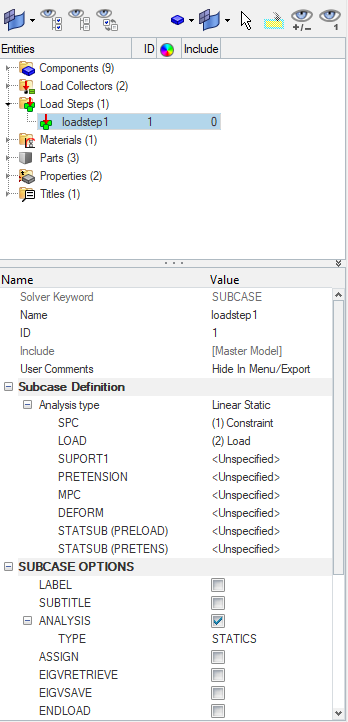
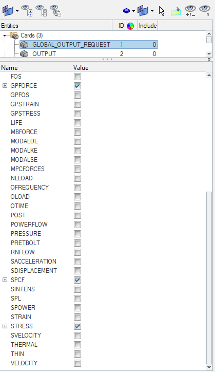
Next, we need to select some control cards like Global_Output_Request, Output, and Param cards.
We will select the Displacement, GP_Forces, SPCF, and Stress for output under the Global_Output_Request, as shown in the image below.
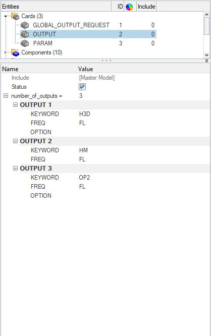
Under the Output Card, we will select three outputs H3D, HM, and OP2 as shown in the image below.
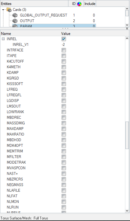
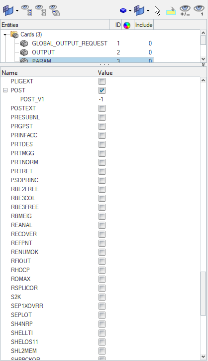
Next under the Param Card, we will select the AutoSPC, Inrel, and Post parameters as shown in the image below.
Performing Analysis
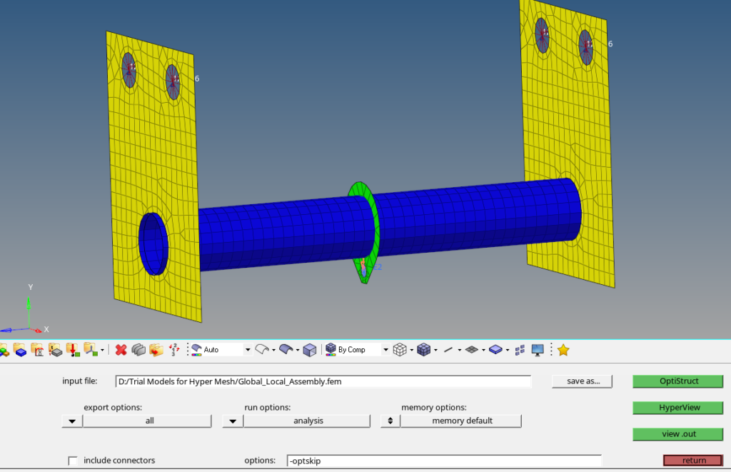
Now we have everything in place. We will perform the analysis. For this we can go to Analysis -> Optistruct select the run options as ‘Analysis’ and then click on Optistruct.
Output
After you click on Optistruct a pop-up window will appear showing the progress of the run.
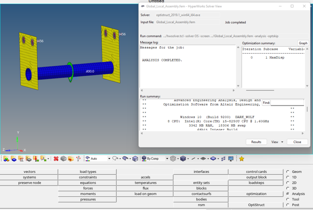
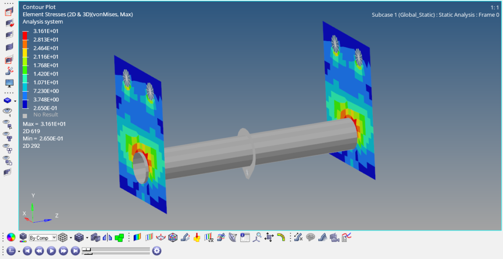
After the run is complete we can click on Results to view the results in Hyperview as shown in the image below.
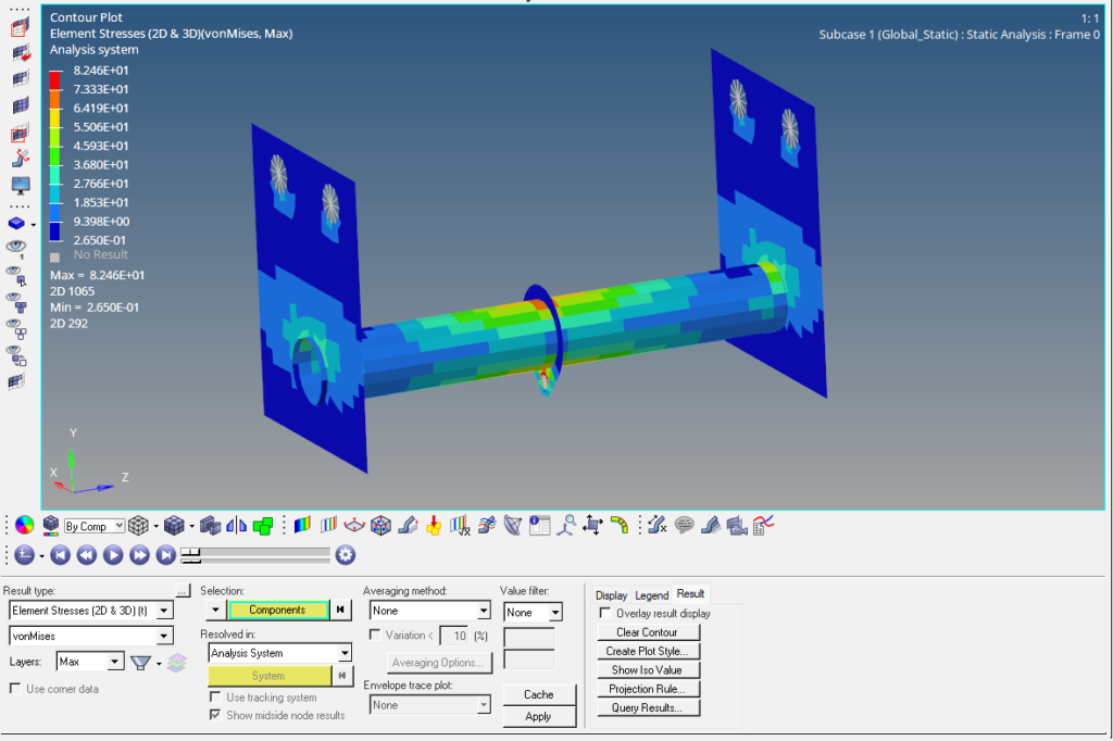
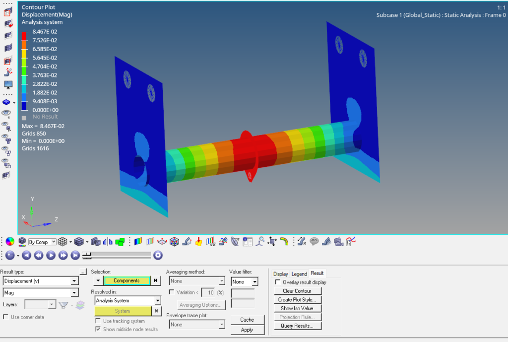
Now we have the Global Results. So what is the next step if we want to perform local analysis?
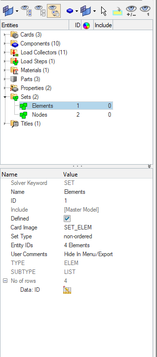
So to perform local analysis we need to get the reactions at the interfaces. For this, we first need to create a set of the elements of the component for which we want to extract the reactions.
For this, we can right-click on the white-browser area and go to Create -> Sets. We will name this set as Elements. Then we can go to Post -> FBD -> and then select the output file generated during the global analysis run, and the subcase, and then click on accept this will create additional load collectors displaying the reactions as shown in the image below.
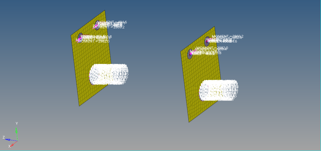
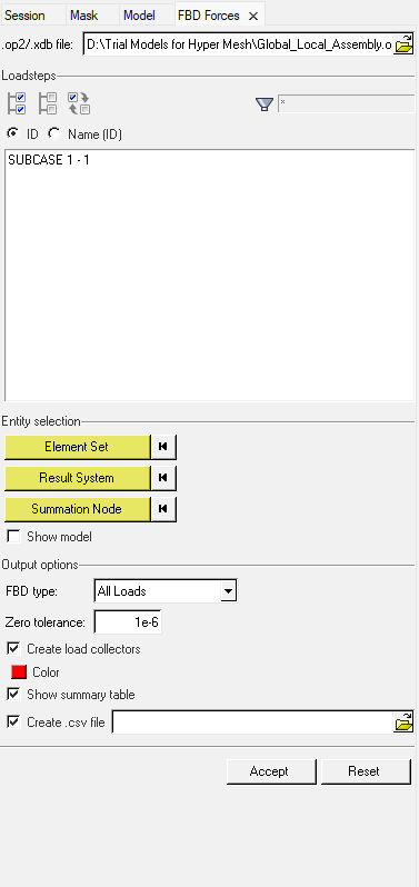
So this is how we can perform a Global analysis and extract the reactions at the component level.
But this is not all, unlike the other tutorials where I have not given you any task. I would like to challenge you to try and perform a separate analysis on this bracket component based on the reactions and compare the stress and displacement results with the global analysis.
Refer to the video below for more clarity on the topic.
This is all for this post. I’ll see you all in the next post. Don’t forget to follow my Facebook and Instagram Pages for regular updates. Until then, keep learning.
