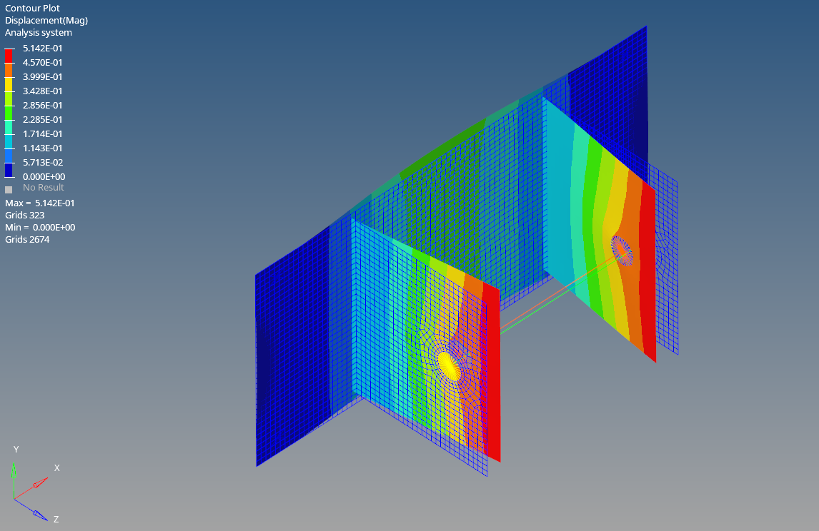
In the previous posts, we have seen about Linear Static Analysis. If you have not seen those posts you can check it out here. In this post, we will see something different from the usual analyses. In this post, we are going to perform a Bolt Pretension Analysis.
So let’s start by understanding what Bolt Pretension is and then we will proceed to perform the analysis.
What is Bolt Pretension Analysis?
Bolt pretension as the name indicates involves applying initial tension to the bolt before any external loads are introduced. This ensures the joint remains tight and stable, even when subjected to various forces and vibrations.
The main goal of bolt pre-tensioning is to create a clamping force that holds the joint together, preventing it from loosening under operational loads. It is used in critical applications such as structural connections, machinery, and automotive assemblies where joint integrity is crucial.
Performing Bolt pretension Analysis
For this tutorial, we will be using a bracket and observing its behavior when a bolt pretensioned bolt is assembled with it.
Meshed Model
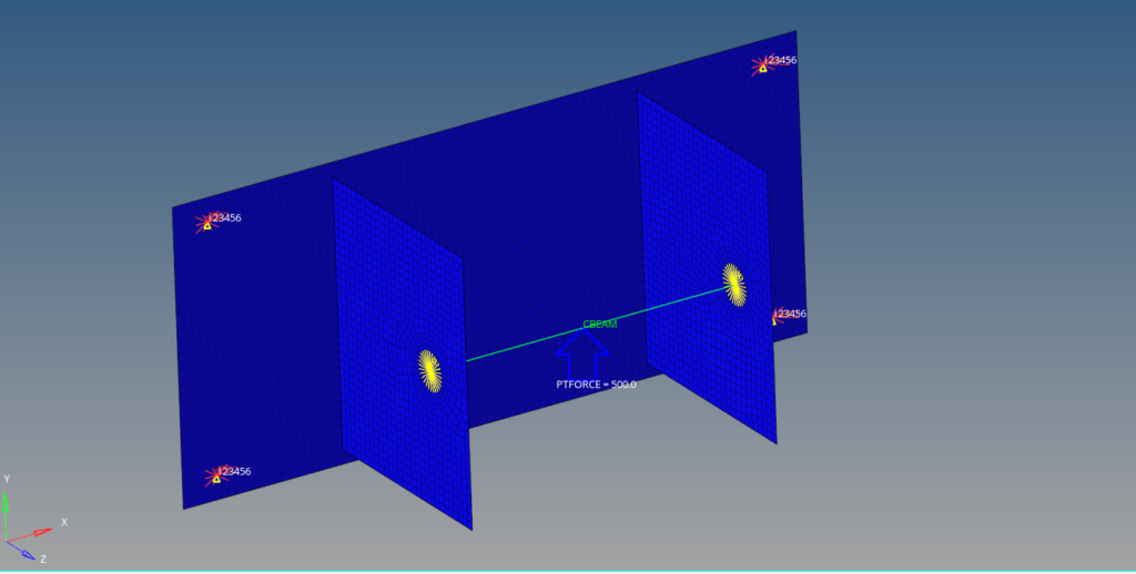
For this tutorial, we will use a bracket with dimensions 164 x 74 mm. The model is meshed using tetra elements of size 2. Next, we will create RBE3 elements to connect the two mounting holes of the bracket with the bolt. We will create the bolt with the help of the beam element as shown in the image below. as shown in the image below.
Boundary Condition
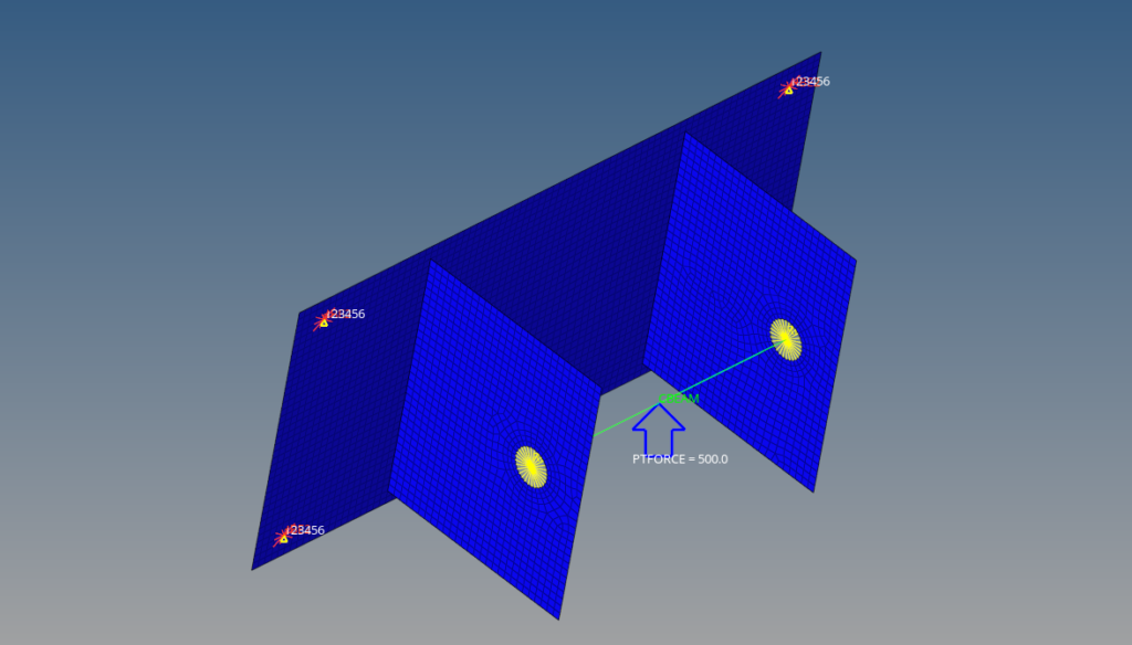
We will create a load collector named constraint to constrain the bracket. We can do this by right-clicking on the white-browser area and then going to Create -> Load Collectors. We will constrain all the degrees of freedom of the four holes of the bracket as shown in the image below.
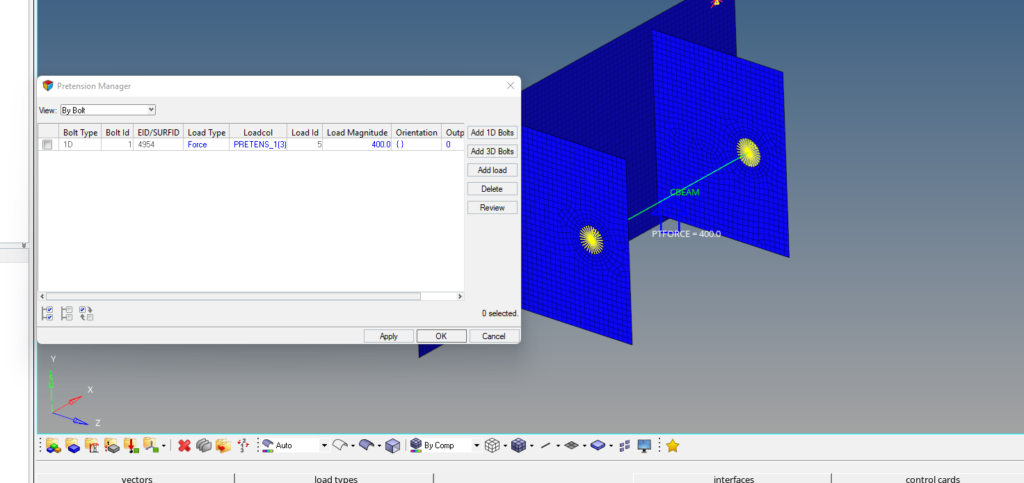
Next, we will create the load collector for pre-tensioning. For this, we can go to Tools -> Pretension Manager. After this, we can create a new bolt pretension load of 400 N. Refer to the image below for more clarity.
Analysis Setup
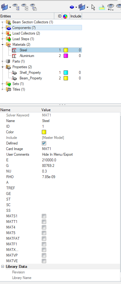
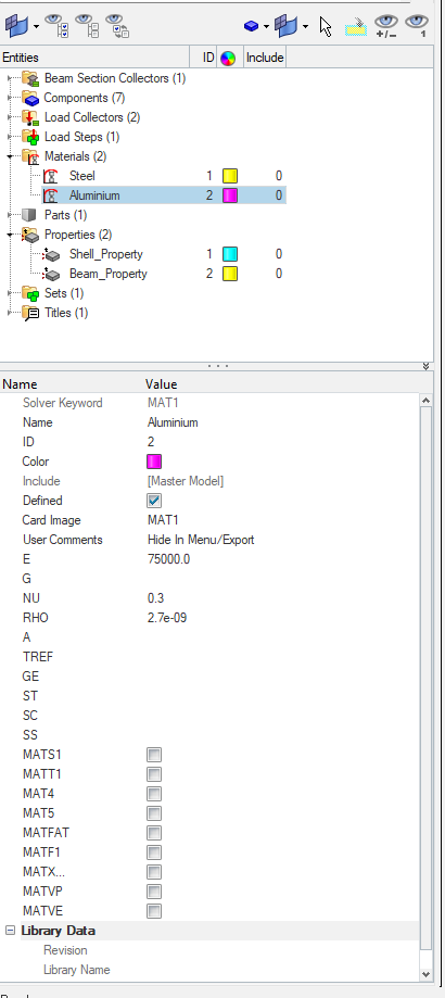
Now we will create material and properties for the bracket and bolt. We will use aluminum material for the bracket and steel material for the bolt.
We can create material by right-clicking on the white browser area and then going to Create -> Materials. We will name one material as Steel and the other as Aluminium as shown in the images below.
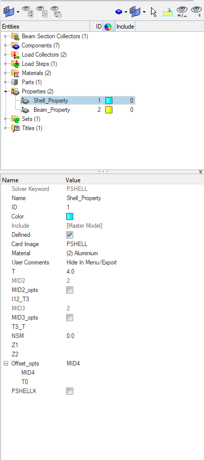
Next, we need to create properties for the bracket and the beam. For this, we can again go to the white browser area and then right-click on the white browser area, and then go to Create -> Properties. We will name these properties as Shell_Property and Beam_Property as shown in the image below.
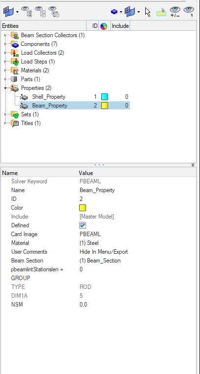
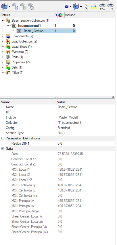
In addition to the above, we need to create a beam section to assign it to the property. We will name this beam section as Beam_Section and assign a radius of 5 to it.
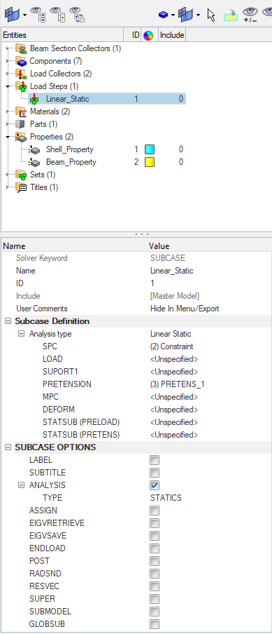
Next, we will assign these materials and properties to the respective components and create a load step for the analysis and name it Linear_Static and reference the constraint and the pretension load collector as shown in the image below.
Performing Analysis
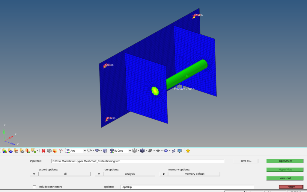
Now we have everything in place. We will perform the analysis. For this we can go to Analysis -> Optistruct select the run options as ‘Analysis’ and then click on Optistruct.
Output
After you click on Optistruct a pop-up window will appear showing the progress of the run.
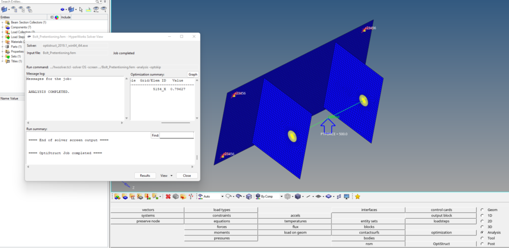
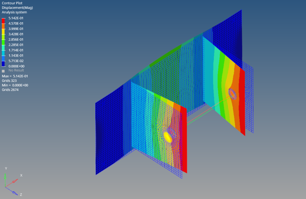
After the run is complete we can click on Results to view the results in Hyperview as shown in the image below.
Refer to the video below for more clarity on the topic.
This is all for this post. I’ll see you all in the next post. Don’t forget to follow my Facebook and Instagram Pages for regular updates. Until then, keep learning.
