This post is going to be a bit different and shorter than the other tutorials. In this post, we are going to see how to apply the moment to a structure.
Before starting the tutorial, let’s refresh some basic concepts.
Right hand thumb rule
This rule states that if we place our thumb along the direction of the moment vector, then curling the rest of our fingers gives the direction of rotation. Refer to the image below for a better understanding.
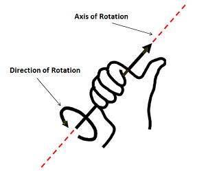
As you can see in the image above the thumb is pointing in the direction of the axis of rotation and the curled fingers give the direction of rotation.
Applying a moment to a structure
In this tutorial, we will be applying the moment to a beam by fixing it at one end.
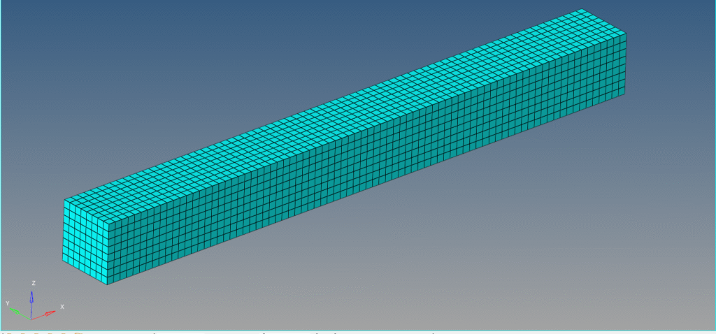
Meshed Model
In this tutorial, we will be using a beam of dimension 8 mm x 8 mm x 80 mm meshed using Quad elements of size 1 as shown in the image below.
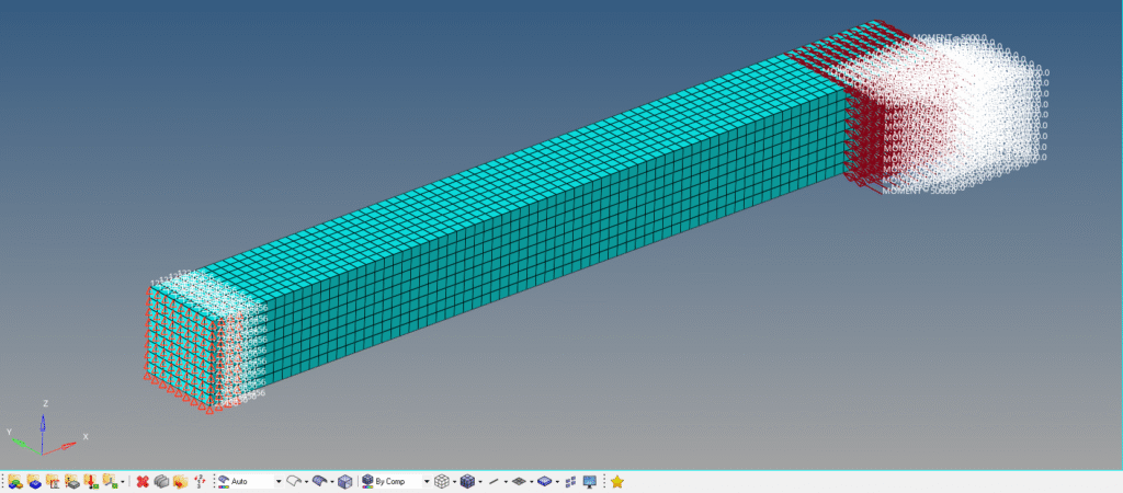
Boundary condition
We will constrain one face of the beam. For this, we can right-click on the white browser area and then go to Create -> Load Collector. We will name this load collector as Constraint. Next, we can go to Analysis -> constraints and select all the degrees of freedom to constrain, and then click create.
Next, we will apply the moment to the beam. For this, we can again right-click on the white browser area and then go to Create -> Load Collector. We will name this load collector Moment. We can now go to Analysis -> Moments and select the nodes on which we want to apply the moment, and then select the direction of the moment. Kindly note that the direction of the moment is the
Analysis Setup
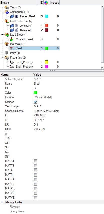
We need to define Property and material for the model. For this, we can right-click on the browser area and then go to Create -> Material and name this material as Steel. We will use the default material steel here as shown in the image below.
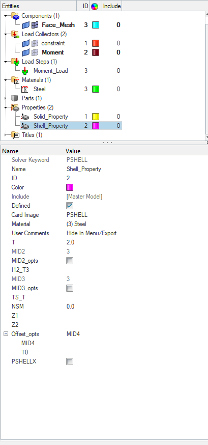
Next, we will create the property for the model. Again, we can right-click on the white browser area and then go to Create -> Property and name this property as Shell property. We will use the shell element thickness of 2.
Performing Analysis
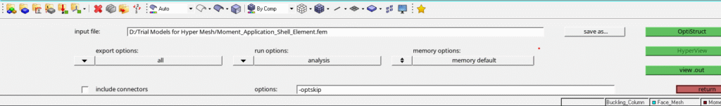
Now we have everything in place. We will perform the analysis. For this, we can go to Analysis -> Optistruct, select the run options as ‘Analysis’, and then click on Radioss as shown in the image below.
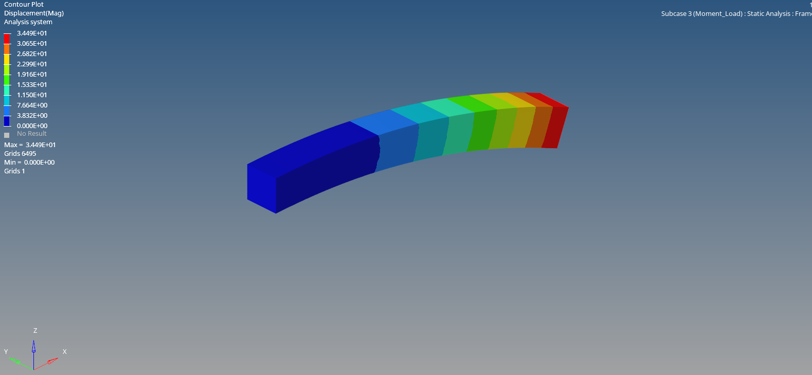
Output
After you click on Optistruct, a pop-up window will appear showing the progress of the run as shown in the image below.
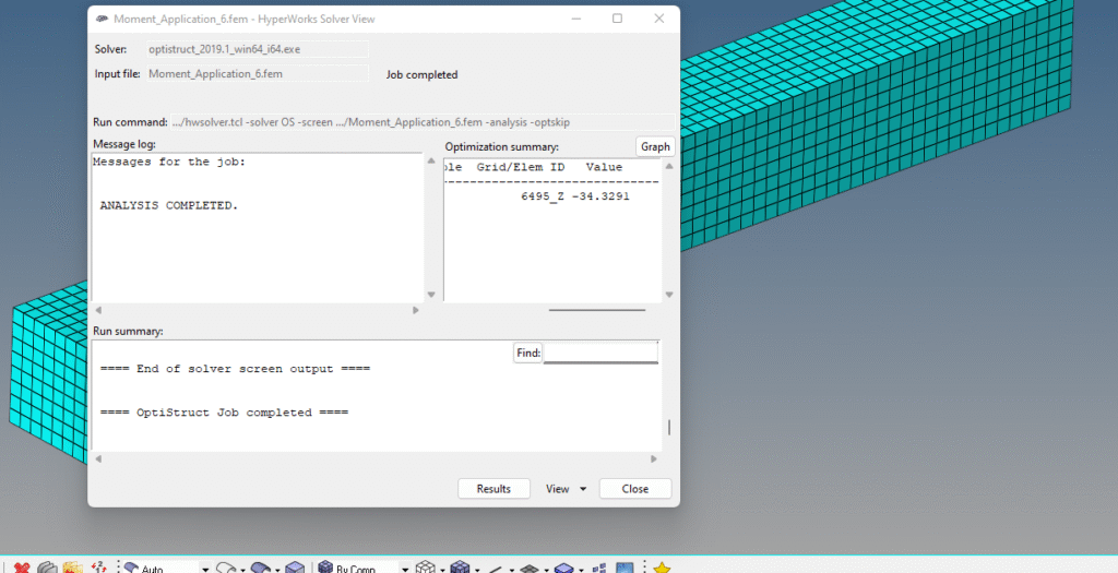
After the run is over, we can click on Results to view the results in Hyperview as shown in the image below.

You can also refer to the video below for more clarity.
This is all for this post. I will see you in the next post. Don’t forget to follow my Facebook and Instagram pages for regular updates. Till then, keep learning.