Till now we have performed analysis using the meshed model in Hypermesh. But did you know that apart from analyzing the model under the given boundary conditions we can also optimize the design of the component using Hypermesh and Optistruct? In this post, we are going to see how to optimize the design of a component using Optistruct.
What is Optimization? Why Optimization?
Optimization by definition is the best or most effective use of the resources available. So optimization in design means to optimize the design such that the design has optimal weight, can be manufactured in the least amount of time, and costs less such that the profit margin can be increased without compromising on the functionality.
Optimization is commonly implemented in the aerospace and automotive industry to design highly lightweight yet robust structural components. This is done to ensure that the lift needed for a level flight is not too high and so that the aircraft can carry more payload.
Topology vs Topography
Topology means dealing with properties of geometric objects that remain unchanged under loading conditions. It is a branch of mathematics. The load can be linear, bending, or torsion load.
Topography by definition refers to the study of the forms and features of any object. In our context, it would mean that it translates to the optimization of the shape of the component.
What is Topology Optimization?
Topology optimization in our context means modifying parts or sections of the component that are not needed from the structural point of view under the given boundary conditions. That is it will change the mass and volume of the component.
Performing Topology Optimization
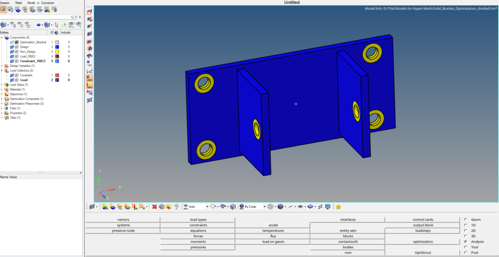
For this tutorial, we will be using the meshed model of a bracket. We will segregate the component into two regions design and non-design region. Design region is the region where mass and volume can be changed whereas a non-design region is the region where mass and volume modification is not allowed. The yellow area in the bracket is the Non-Design area and the blue area is the Design area.
Meshed Model
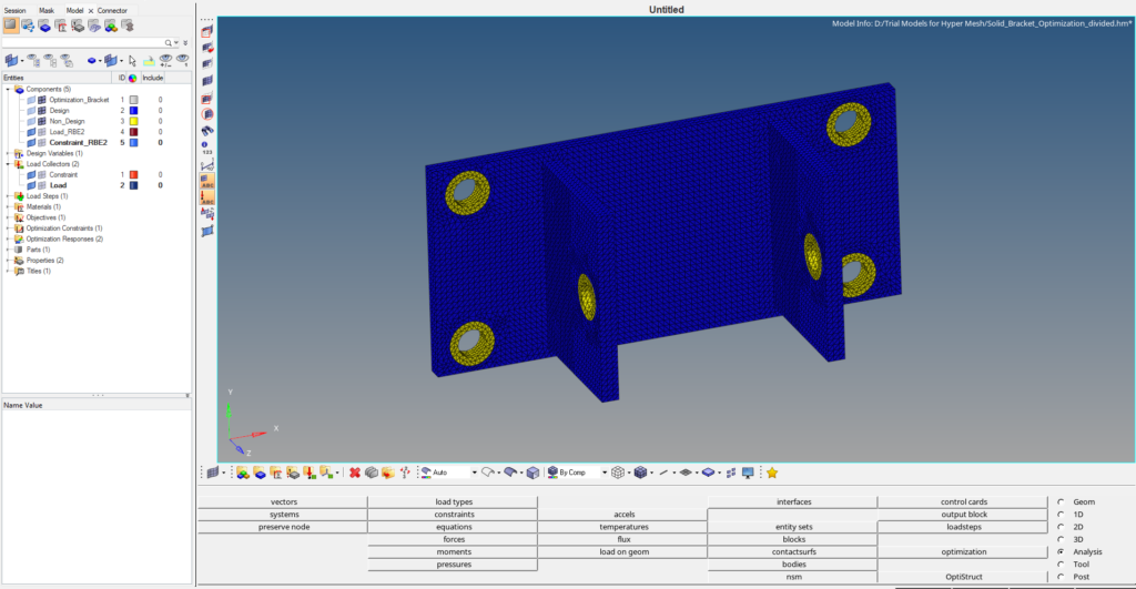
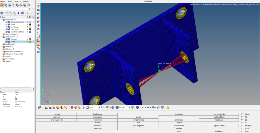
For this tutorial, we will use a bracket with dimensions 164 x 74 mm. The model is meshed using tetra elements of size 2. The geometry will be divided into two regions Design and Non-Design regions as shown in the image below. The holes on which load and constraints will be applied will be kept under the non-design region, and the rest of the body will be kept under the design region.
Boundary Condition
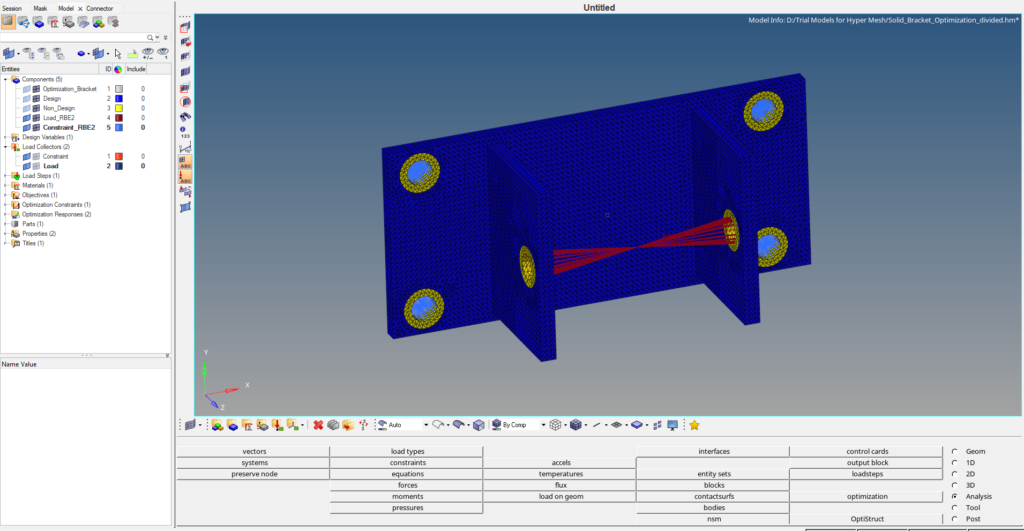
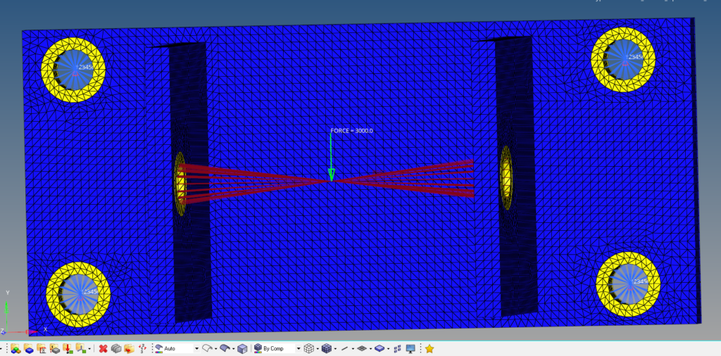
We will create two load collectors one for applying load and the other for applying the constraints. We can create a load collector by right-clicking on the white browser area and then going to create -> Load collector. Next create a load collector named Load. We will then apply a force load of 3000 N in the negative y direction on the RBE2 element created on the two holes as shown in the image below. We can create force load by going to Analysis -> force.
Next, we will create a new load collector by right-clicking on the white browser area and then again going to Create -> load collector. We will name this load collector constraint. We can create constraints by going to Analysis -> constraints. We will apply these constraints to the four holes on the flat face as shown in the image below.
Analysis Setup
Now we have to create materials, properties, design variables, responses, constraints, and objectives for the optimization. First, we will create material and property by right-clicking on the white browser area and then going to Create -> Material. We will use steel as our default material.
For creating property we can again right-click on the white browser area and then go to Create -> Property. We will create two properties Design and Non-Design, both with card images as PSOLID.
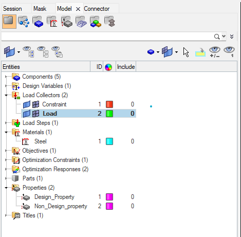
We will create a load step by right-clicking on the white browser area and then going to Create -> Load Step. We will name this load step as Static analysis and select the analysis type as Linear Static and reference the constraint under the SPC and the Load under the load field. If you want to learn about Linear Static Analysis you can check out this post here.
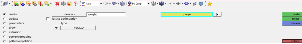
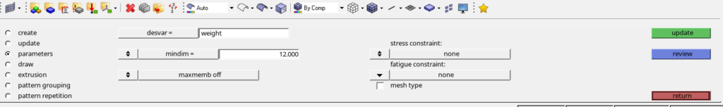
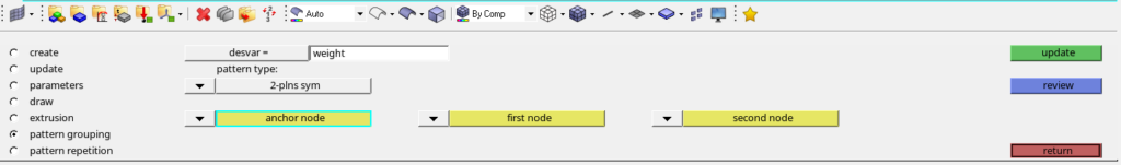
We will then create a topology design variable by going to Analysis -> Optimization -> Topology. We will name this variable as weight. We have to select the property of the Design part while creating this variable. I have used minimum dimension as 12 under parameters and 2 plane symmetry under pattern grouping. Refer to the image below.
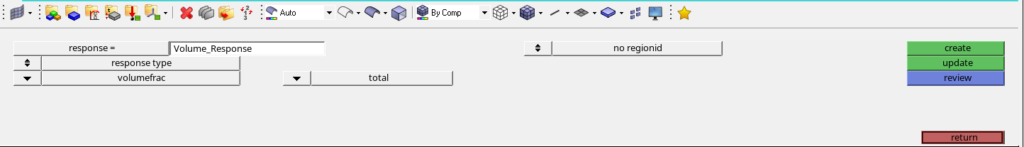
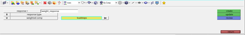
After this, we will create responses for this optimization. For creating responses we can go to Analysis -> Optimization -> Responses. We will create two responses one for weight and one for volume as shown in the image below. We have to select the loadstep in weight response.
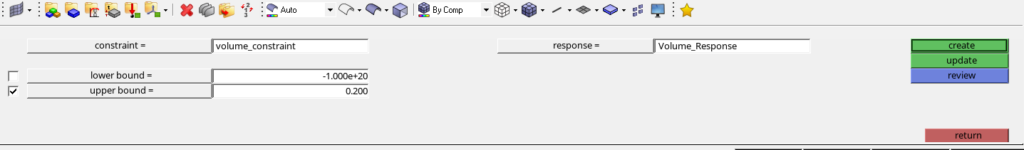
Next, we will create constraints for the optimization. We can do this by going to Analysis ->Optimization -> Constraints. We will create constraints according to the image shown below. I have chosen the upper bound to be 20% of the initial value.
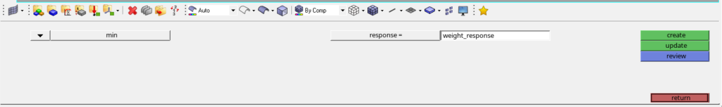
Next, we will create the objective for optimization. We can do this by going to Analysis -> Optimization -> Objective. We will name this objective as objective. Refer to the image below.
Performing Optimization
Now we have applied the boundary conditions and created the variables necessary for optimization. We can now proceed to run the Optimization. For this, we have to go to Analysis -> Optistruct. Then select export options as all and the run options as optimization and click on Optistruct to run the optimization as shown in the image below.
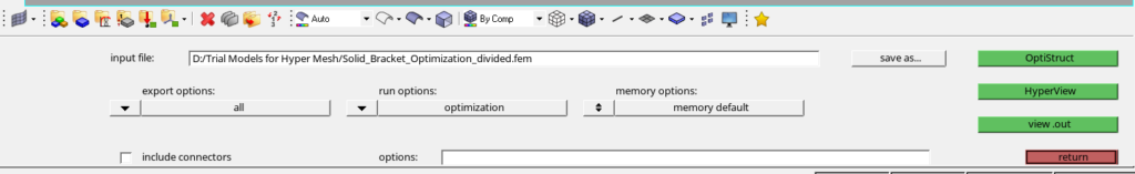
If you can’t see the optistruct option go to Preferences -> User profile and select optistruct.
Output
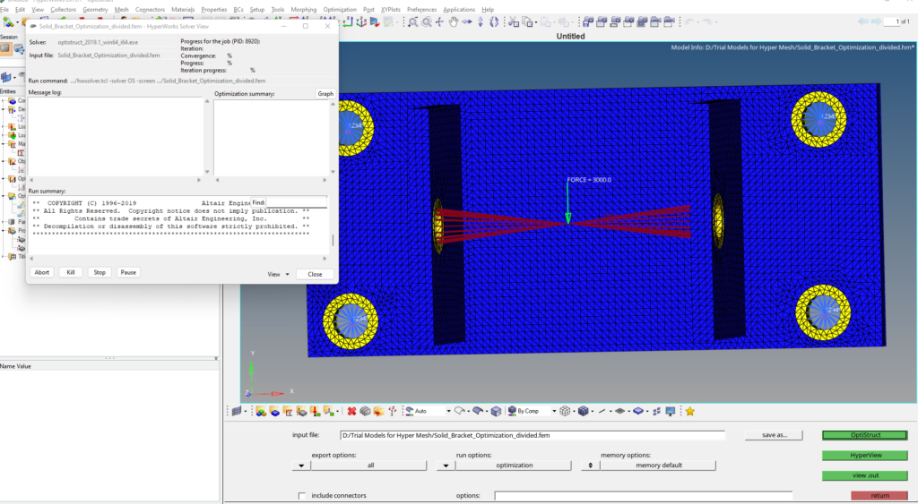
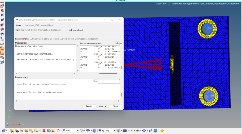
After you click on Optistruct a pop up window as shown in the image below will appear.
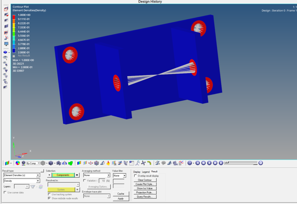
After the run is complete we can view the results by clicking on results. A pop up window of hyperview will open as shown in the image below.
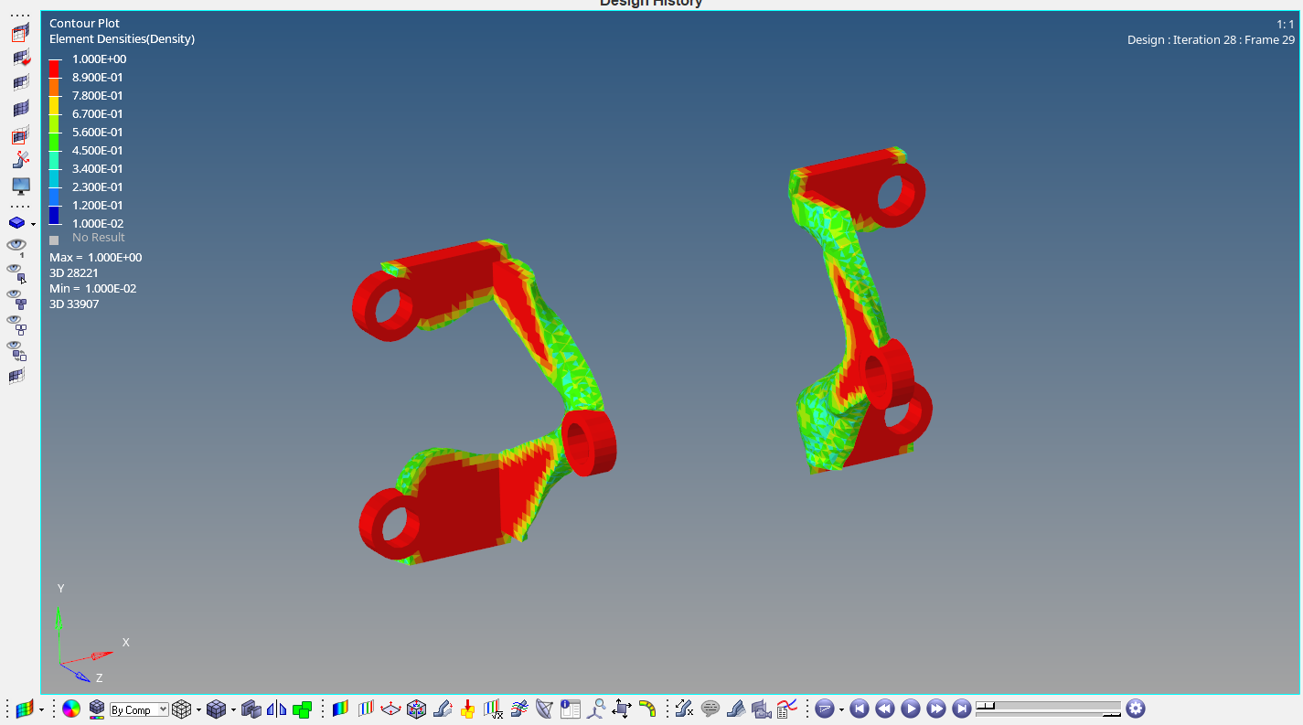
As you can see from the image below the extra mass has been removed by the last iteration. We can take this given volume in consideration and redesign the component.

Refer to the video for more clarity on the Topology optimization.
This is all for this post. Comment your thoughts below. Don’t forget to follow my Facebook and Instagram pages for regular updates. See you all in the next post. Till then keep learning.