In this post, we are going to learn and perform modal analysis in Hypermesh.
So we will be starting with knowing what is modal analysis, preparing a model to observe its modes of vibration, taking a lumped mass and connecting it to the model and then performing modal analysis, and finally comparing the results. Before diving into the tutorial we need to get familiar with some terms
Modes and Mode shapes
To understand Modal Analysis we first need to understand what are modes and mode shapes. So modes are the specific vibration pattern or natural frequency of a structure. You can read more about modes here. Modal frequency or the frequency character of the mode tells us how fast the structure vibrates at that specific mode. Modal Shapes are hypothetical deformations described by our finite element model for each of the modes.
Stiffness and Natural Frequency
Stiffness is the resistance of an elastic body to deformation caused by an external force. Natural frequency or resonant frequency is the rate at which the body vibrates in the absence of any external load. The relation between the stiffness of the body and frequency of a body is defined as follows:
f = sqrt (k/m)
where f is the frequency, k is the stiffness of the body, and m is the mass of the body.
Why is Modal Analysis needed?
As with any analysis, there should be a reason to perform this type of analysis. There can be several reasons to perform this analysis some of them being to check the connections to determine if there are rigid modes in the system, rigid modes here means the modes in which the body doesn’t deform but goes into translation or rotation motion; to study the behavior of the system under dynamic loads; to check for resonant frequencies; to check the correctness of the constraints, etc. You can read more about modal analysis here.
Performing Modal Analysis
For this tutorial to perform modal analysis we will be using a lumped mass connected to a plate. A lumped mass in short represents the mass of a body through a point mass, that is the mass of the body is concentrated at that point.
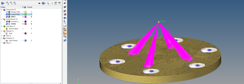
So to summarise the step-by-step process, we will start by making a vibration plate model as shown in the image below, we will create and material for the meshed model, then we will create a lumped mass, then we will assign contraints and connections, and finally perform modal analysis.
Meshed plate Model:
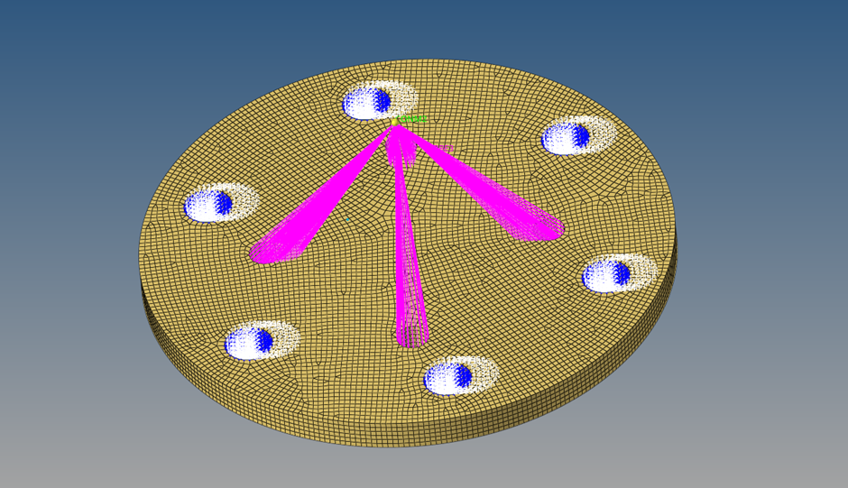
For this tutorial, I have used a 12 mm thick plate as shown in the image below. The plate has four holes for connecting the lumped mass and six holes for fixing it. You can keep the plate dimensions according to your choice or use the dimensions mentioned.
Lumped mass
In this step, we will be creating the lumped mass and connecting it to the plate. To create the lumped mass we first need to create a node. To create the node we have to go to Geom -> node. Then translate the node to a height of 48 mm from the center of the plate. Then assign the mass to it. To assign mass to the node we need to go to 1D -> masses. We will assign a mass of 60 Kg to the mass. Kindly note that the unit of mass in Hypermesh is tonne, so we have to enter the value of mass as 0.06 in the mass field.
To connect the mass to the plate we will use rbe3 elements. To do this we will first create a component collector with the name RBE3. To create rbe3 elements we can go to 1D -> rbe3 and select the inner face of the four holes on the same pitch diameter as shown in the image in the previous section.
Boundary Conditions
To apply constraints we will first need to create a load collector, we will name this load collector constraint. Then we will fix all the degrees of freedom of the six holes near the circumference of the plate. For fixing these holes we will select the inner face of these holes. To apply constraints we can go to Analysis -> constraints.
We are not going to apply any loads in this analysis as there is no external excitation coming. So how are we going to extract the modes of the vibration of the plate and lumped mass if there is no external load? The answer to this is we are going to extract the natural frequencies of the plate and lumped mass assembly.
For this, we will need to create a separate load collector named EIGRL and select its card image as EIGRL. To create this load collector right-click on the white browser area and go to Create -> Load collector. This load collector will help us extract the modal frequency of the different modes. For this tutorial, we will use ND as 6 for the EIGRL load collector. ND here is the number of modes.
Analysis Setup
We have to now apply material, property, and create load step.
Create a PSOLID property by right-clicking on the white area on the browser area and selecting Create -> Property, then select the card image as PSOLID and assign this property to the plate component.
Then create a material by right-clicking on the white browser area and going to Create -> Material, we will use steel for this tutorial, the values of steel are available by default in Hypermesh.
Then create a Load step by right-clicking on the white browser area and going to Create -> Load Step. Name the load step as Modal Analysis and select the Analysis type as Normal modes. Select the constraints load collector under the SPC field and the EIGRL load collector under the method (struct) field. Once completed the browser area will look very similar to the image below.
Performing Analysis
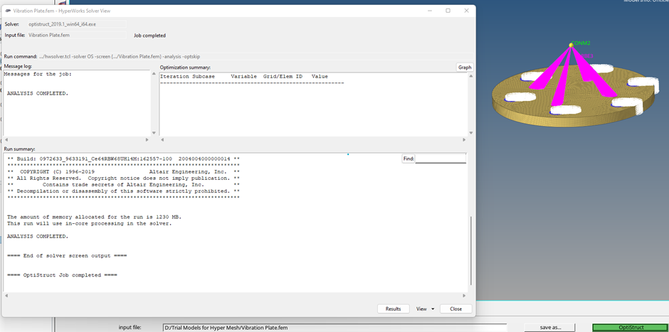
To perform the analysis, we will go to Analysis -> Optistruct, and a window similar to the below image will appear. Kindly note that we are using Optistruct for this tutorial and you can use any other solver of your choice too.
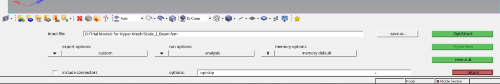
If the optistruct option is not appearing under Analysis in the toolbar. Then go to Preference -> User Profile and select Optistruct. Select export options as custom, run options as Analysis, and keep the memory option as default. Then click on Optistruct to run the analysis. A pop-up window will appear displaying the progress of the run as shown in the below image.
Output
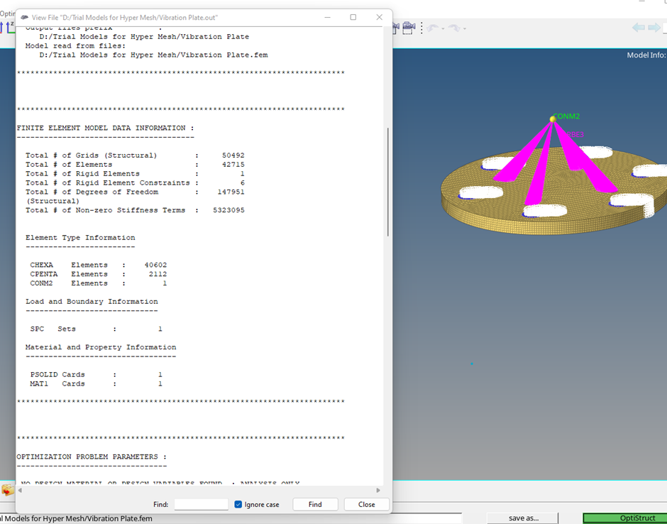
Once the solver run is completed we can view the output values we can also go to View -> Output file as shown in the image below.
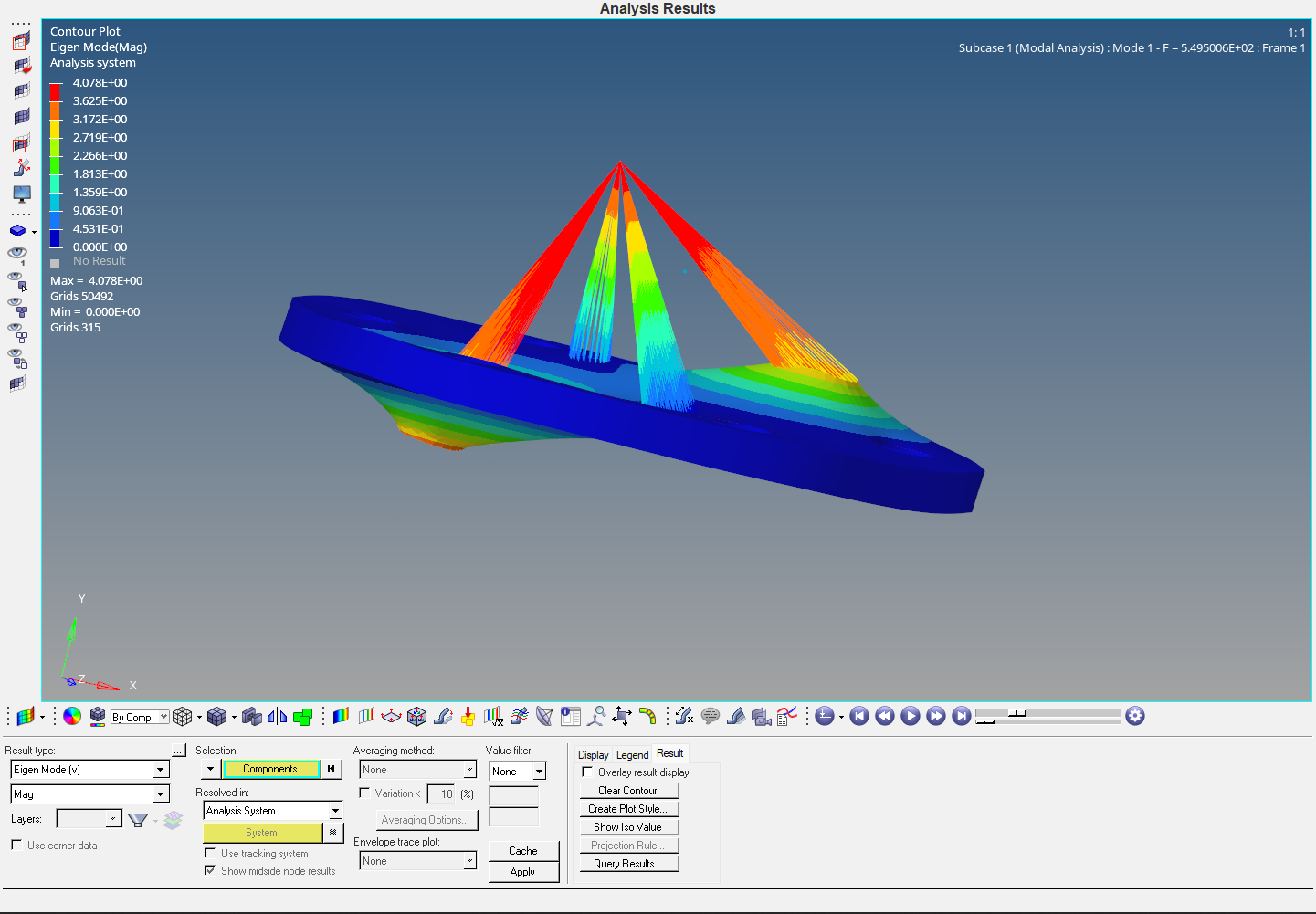
Click on Results to view the results of the Analysis as shown in the image below. A window like the below image image will open. This is the Hyperview window and is used to see the results of the analysis. If you don’t know about this don’t worry I will be making a separate post on this.
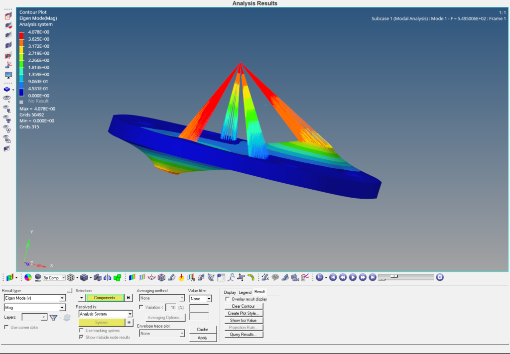
As can be seen in the above image we can visualize different modes of vibration for the plate. So to summarise all the steps:
- Import geometry and mesh it.
- Create a lumped mass and connect it to the plate.
- Apply Boundary conditions
- Apply Material and Properties
- Create the load step and run the analysis
- View the result in Hyperview
You can also refer to the below video for more clarity on the topic.
This is all for this post see you all in the next post. Don’t forget to follow my Facebook and Instagram Page. Till then keep learning.