
In the previous post, we have seen about HyperLaminate. In this post, we are going to see how to use it to model composites and analyze them.
Just to recap HyperLaminate is an additional module in Hypermesh used to create laminates, particularly for composite modelling and analysis.
There are 2 two types of laminates we can create in Hypermesh which are described below:
- Zone-based laminate: In a zone-based composite model, the model is divided into several zones and each laminate zone requires a separate property to be defined. Any change in stacking or plies requires redefining the zones. Refer to the below image to understand zone-based laminates.
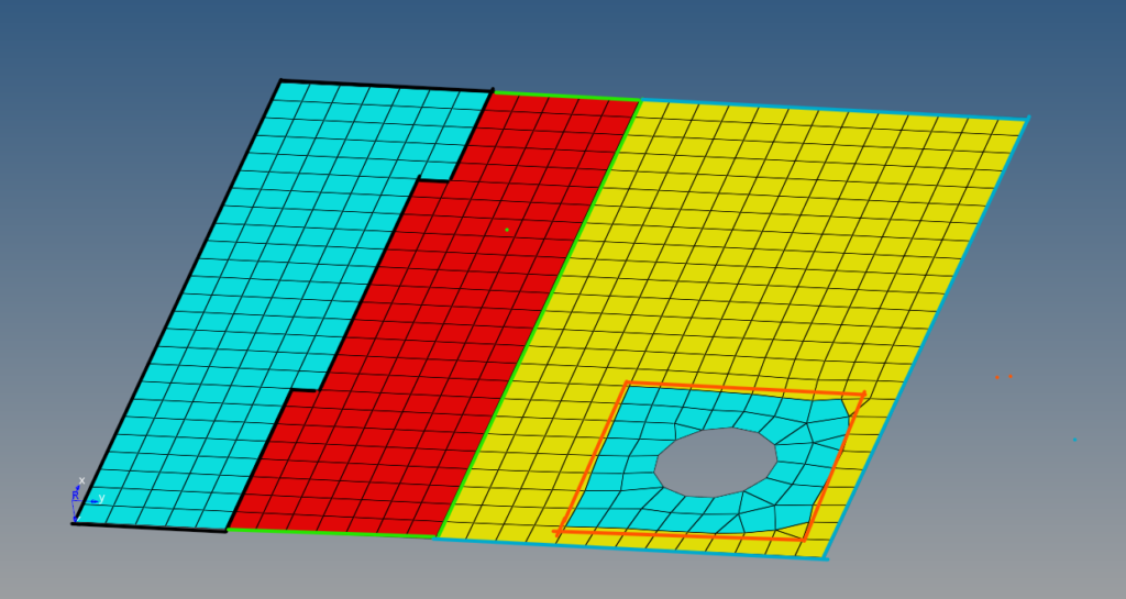
The area enclosed with a black line is Zone1, the area enclosed with a green line (red) Zone2, the area enclosed with a blue line (yellow) is Zone3 and the circular area enclosed with an orange line (blue) is Zone4.
2. Ply-based laminate: In the ply-based composite model, the model doesn’t consist of different zones, instead it is a single entity. Property needs to be defined only for the base structure and not for zones. Refer to the below image to understand ply-based laminates.
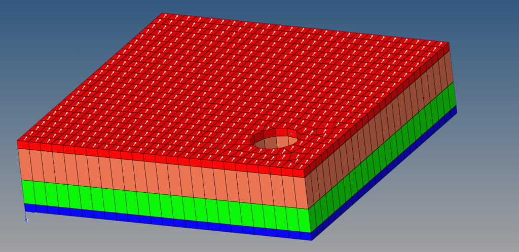
So in short the difference between zone-based and ply-based modeling is that in zone-based modeling the property, orientation, and thickness can vary within the same layer, whereas in ply-based modeling the property, orientation, and thickness remain the same throughout the layer.
We will start with Zone-based modeling. Hyperlaminate helps us with defining zone-based laminate. To access the HyperLaminate option we can go to 2D -> HyperLaminate.
Upon clicking the option a new window opens up for HyperLaminte as shown in the image below:
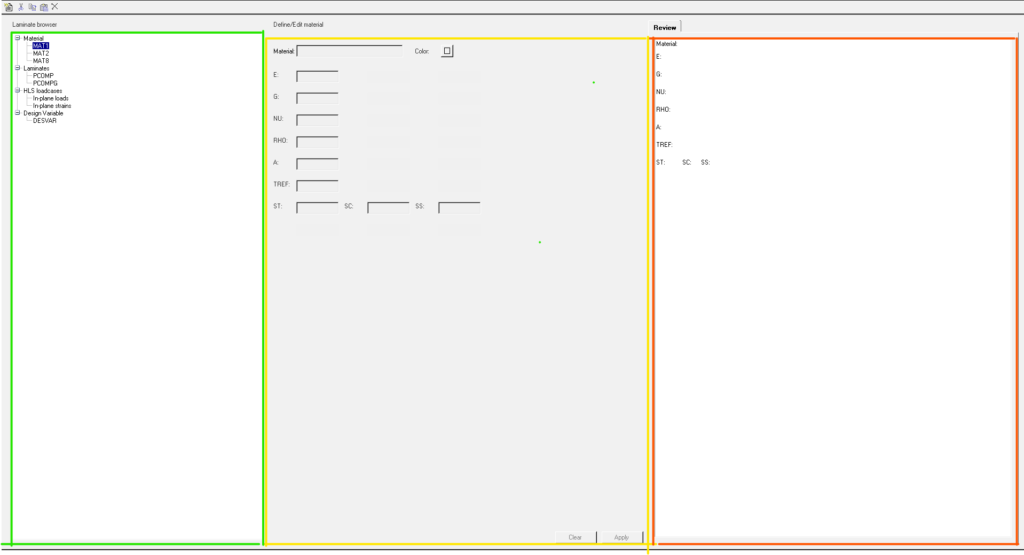
Here we have different options on the left-hand window bordered in green color in the above image. Let’s explore these options.
- First, we have the option to define the material for composite layers. The material card images available for making the material are MAT1, MAT2, and MAT8. If you want to know what these card images are, you can read more about them here. These materials can be carbon fiber, glass fiber, etc. We have to enter the E, G, NU, and Rho values for each of the materials we declare.
- Second, we have the option to declare the property for the materials we define above. The card images available for this are PCOMP and PCOMPG. You can read more about the property card images in Hypermesh here. So there are three property card images usually used to create laminate structures. PCOMP and PCOMPG are used to create zone-based laminate, while PCOMPP is used to create ply-based laminate.
- Third, we have the option to create HyperLaminate load cases. HLS load cases help us to create load cases to test the laminate we have created.
- Fourth, we have the option to create design variables.
Zone-based laminate modeling:
We will start by creating 3 materials for our composite model according to the below details. We will use MAT2 card image to create these materials with dummy values.
Material 1: Input G11:4; G12:6; G13:8; G22:10; G23:12; G33:14; RHO: 2.4
Material 2: Input G11:16; G12:12; G13:10; G22:8; G23:6; G33:4; RHO: 2.6
Material 3: Input G11:24; G12:26; G13:28; G22:30; G23:32; G33:34; RHO: 1.8
Kindly note that these are dummy values and should not be considered for analysis under any circumstances.
To create the material select the MAT2 card image and right-click and select New to create a new material with card image MAT2.
Laminate creation:
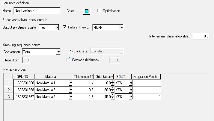
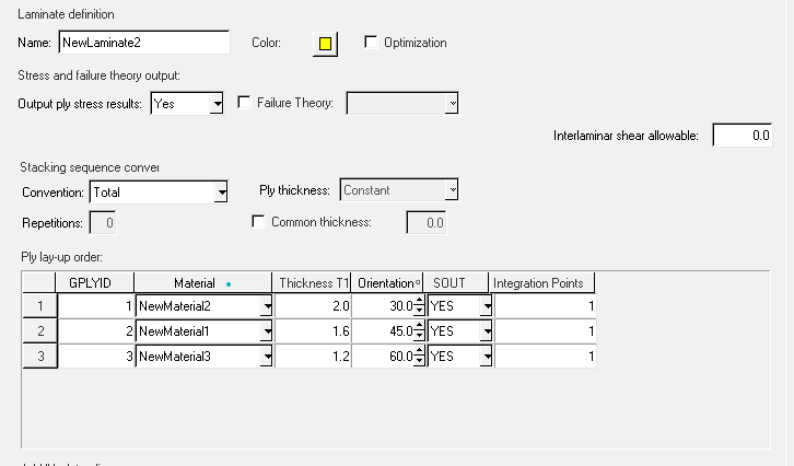
Select the PCOMPG card image under the laminate and click on new or right-click and click on new. Then add the materials created in the above step in whichever order you prefer. For this tutorial, we will arrange it according to the image shown below:
For the first type of zone:
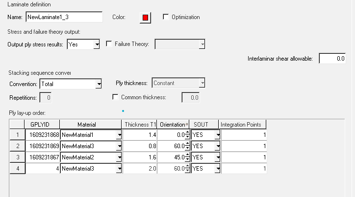
For the second type of zone:
The third type of zone:
Loadcase creation:
Here we can define the in-plane stress and strain and use them to visualize the stiffness/Material Matrix value, mid-plane results, Global system results, principal results, and Invariant results.
Now we have created the materials and the laminates for different zones for the composite model but how to apply them to one model. For this, we have to assign these properties to the selected elements. For more clarity, you can refer to the below video.
PLY-based laminate modeling:
For this, we will use the same materials created above. To make a ply-based model we have to make plies separately and then stack them up in a separate laminate.
So we will make a ply by right-clicking on the browser area and going to create->Ply and creating separate plies for separate materials. Here we have to select the material type, material, system, and the elements to which these plies would be applied and fill the thickness and orientation of the ply.
Then we will create laminates by right-clicking on the browser area and going to create->Laminate, and then adding these plies to these laminates.
Now creating the laminate is not enough. To visualize these laminates with all the layers we need to create a PCOMPP property. Then we have to assign this property to the base mesh component.
To have a better understanding of the above processes you can refer to the below video:
This is all for this post. Don’t forget to follow the Facebook and Instagram pages for regular updates. See you all in the next post. Till then keep learning.