In this post, we are going to look at connectors and contact surfaces.
Connectors:
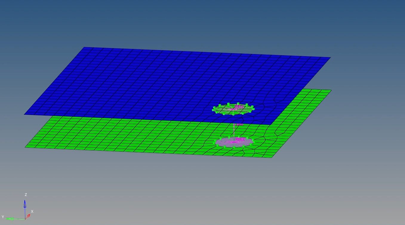
Ever wondered how we connect meshed components, i.e. weld or bolt joints, in Hypermesh?
One of the ways to connect components is manually using RBE2, RBE3, or CBEAM which we will be discussing in a later post. For now, we are going to look at the connectors option available in Hypermesh.
Connectors are used to connect components. The connectors option can be accessed by going to 1D/2D/3D -> connectors. There are different options for connection available under this such as spot, bolt, seam, and area.
Before seeing the above options in detail, it is a must to understand the different color coding of the connectors.
- Yellow – This means the connector is in an unrealized state. What does this mean? This means the connectors are only a geometric entity now and not a part of the FE model.
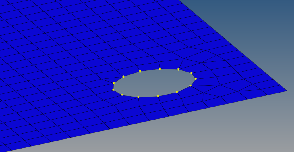
Unrealized connectors
- Green – This means the connector is in a realized state and is a part of the FE model now.
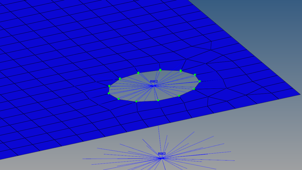
Realized connectors
- Red – This means the connectors failed to realize, i.e. it failed to be converted from geometric to FE entity.
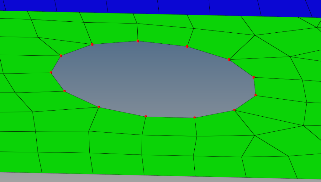
Failed to realize
- Blue/Purple – This means the connector has been modified. Either the property, nodes, or the component input could have been modified.
Now let’s look at the different options and input fields available under the different connection options. If we open any one of the connectors option the options available are the same. We will take spot weld as an example under this we have the following options:
- create – This option is used to create connectors based on the node, component, number of layers, and tolerance input data. This creates only the geometric representation of the connectors.
- realize – This option is used to realize the created connectors. The input data for this is the created connectors, type, property, and diameter. Once exercised this option creates an FE entity for the connection.
- edit – This option is used to update the connector spacing/ density and offset. The updated connector will appear in blue/ purple color, we have to re-realize the connector.
- Spot – This option is simultaneously used to create and realize a connector.
We can check the status of all the connectors in a model through the connector browser. We can access the connector browser through View -> Browsers -> Hypermesh -> Connectors.
You can also refer to the below video for more clarity on connectors.
Contact Surfaces:
Till now we have seen how to connect components in the Hypermesh model for bolt and weld joints. But what about components in which the components are sliding, rolling, etc.?
We can access the contact surfaces option through Analysis -> Contact Surfs.
The different options available under contact surfaces are:
- Elements – This option is used to create contact surfaces between 2D elements. The input fields for this are name, card image, and face angle.
- Solid faces – This option is used to create contact surfaces between 3D elements. The input fields for the same are name, card image, and face angle.
- Remove elements – This option is used to remove contact surfaces. The input field for this is contact surfaces.
- Adjust normal – This option is used to change the direction of the contact surface normal.
Creating contact surfaces is not enough, the creation of contact surfaces only indicates that these surfaces are meant to be connected, but doesn’t say which surface needs to be connected to which surface and what is the connection type. To realize contact surfaces, i.e. to map the contact surfaces we have to create contacts. This can be done by right-clicking on the browser, going to Create, and selecting Contact.
To realize a contact, we need to provide the following inputs in the respective fields:
- Card Image – This should be set to contact if you using this to define the contact between contact surfaces.
- Property option – Generally I use property type under which we have different options slide stick and freeze.
- SSID – This stands for slave ID. One of the surfaces should be defined as slave and the other as master. Generally, the slave surface is less stiff or moving.
- MSID – This stands for Master ID. Generally more rigid or fixed surface is defined as master.
Contact surfaces are primarily used for contact analysis.
That’s all for this post, see you all in the next post. Don’t forget to follow my Facebook and Instagram pages for regular updates. Till then keep learning!